Ultrasonic machining and reconfiguration of braking surfaces

a technology which is applied in the field of ultrasonic machining and braking surface reconfiguration, can solve the problems of reducing the service life of the braking surface, and encouraging fatigue cracks, so as to increase the service life and increase the braking service strength

Inactive Publication Date: 2002-10-01
UIT LLC
View PDF12 Cites 30 Cited by
  • Summary
  • Abstract
  • Description
  • Claims
  • Application Information

AI Technical Summary

Benefits of technology

It is a general objective of the present invention to provide improved methods of machining metallic braking surfaces, typically cast iron by way of ultrasonic machining of the braking surfaces to restructure the surface strength and topography in a manner significantly increasing braking service strength and life.

Problems solved by technology

These tooling marks and tensile stresses limit the active service life of the braking surfaces thus encouraging fatigue cracks by heat checking and scuffing.
For example, such roughened braking surfaces require an intense burnishing process which develops heat checking when confronting the topography of brake pad surfaces thus encouraging heat checking hot spots which reduce the service life of the braking surface.
Furthermore, because of the nature of the product, particularly the confined and inaccessible interior braking surfaces of cast iron brake drums, it is physically difficult with peening methods to rework the braking surface areas without overlapping onto adjacent surfaces.
Also precise and uniform control in the peening process to repeatedly meet different braking surface specifications is rarely feasible and practically impossible, thus leading to a low reliability of the peening method.
However, the disclosed method and equipment would not be operable for processing the heavy cast iron structure used in brake drums and rotors, nor would it be able to process the sub-surface material to the depths needed for meeting braking surface specifications.
Prior ultrasonic impact treatment methods have been utilized for treating weld joints and fractures in structural iron, but it has not been known how to treat the topography and strength of braking surfaces ultrasonically to obtain greater strength and ability to perform the in-service role of compressively confronting brake pads.
Prior art brake drums are in general subject to thermo-mechanical fatigue, and propensity to develop cracks.
The braking surfaces between drums and brake pads do not have appropriate shape and texture for service and thus need be subjected to extensive break-in procedures which themselves tend to produce cracking and thermo-induced stresses.
The peening method of brake surface treatment leaves a roughened braking surface that reduces the amount of effective area of the braking surface in use, produces uneven distribution of individual peened peaks and contact area sizes to thus have the propensity to develop hot spots, thereby seriously limiting the maximum braking moment and contributing to early fatigue failures.
Further significant limitations of the peening method include the depth of allowable wear on the working surface and the uniformity of braking characteristics during the life of the brake drum.
One further limitation of the peening method is the inability to control the process to meet variable specifications.
For example, the only control over braking surface roughness is the complicated matter of finding and implementing the appropriate shot sizes and accompanying striking forces.
There is essentially no way to achieve a smooth cylindrical interface fit with an associated brake pad with the peening method.
However, this teaching does not disclose a feasible system for the reworking of machined metal work pieces by ultrasonic machining methods in a manner reworking the sub-surface crystalline structure and establishing the surface texture of a metal workpiece, as does this present invention.
This system does not disclose how to successfully apply ultrasonic energy to correct braking problems by machining brake drum surfaces.

Method used


Image

  • Ultrasonic machining and reconfiguration of braking surfaces
  • Ultrasonic machining and reconfiguration of braking surfaces
  • Ultrasonic machining and reconfiguration of braking surfaces

Examples


Embodiment Construction

This invention in general introduces novel methods and equipment for machining metallic cast iron brake rotors and brake drums with ultrasonic machining methods for significantly increasing the braking surface available for braking service. In this process, braking surfaces and the adjacent sub-surface regions are plastically altered to remove tooling marks and produce an interfacing surface of specified macro and micro smoothness features better mating with an associated brake pad.

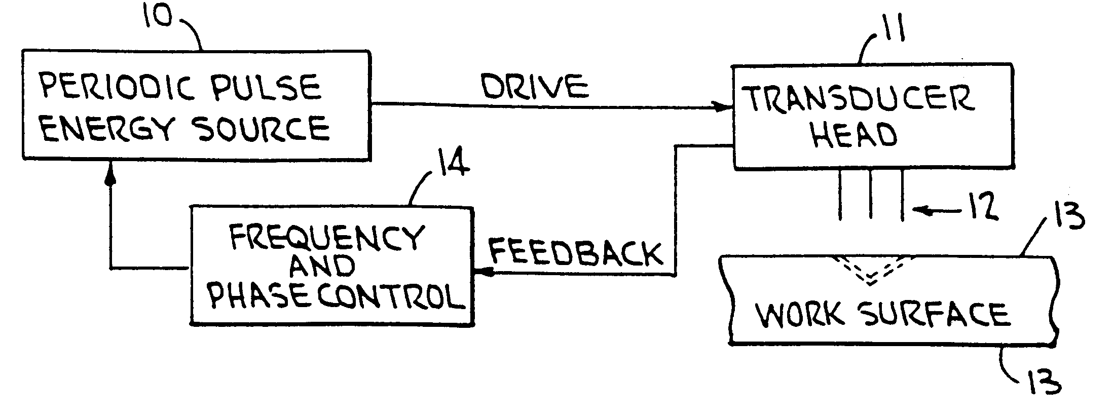
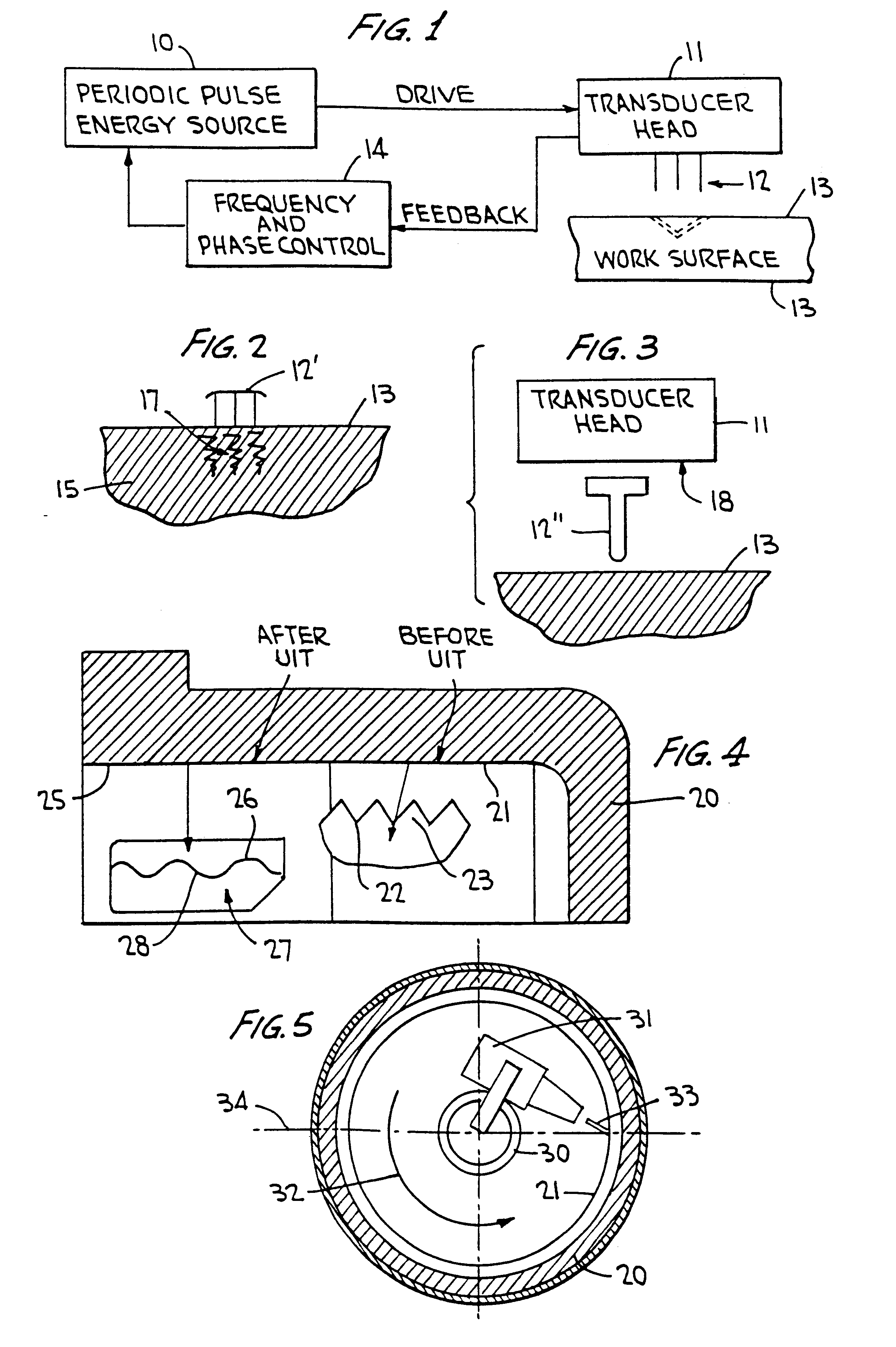
With reference to FIG. 1 of the drawings, this block system diagram identifies the ultrasonic impact operating system for treating rotary braking surfaces at work surface 13, from ultrasonically movable impacting members 12 presenting a set of several, typically three or four, spaced members for impacting the work surface 13 under control of the ultrasonic transducer head 11. The periodic pulse energy source 10, typically operable at ultrasonic frequencies up to 55 kHz drives the transducer head 11, prefe...


PUM

PropertyMeasurementUnit
resonant oscillation frequencyaaaaaaaaaa
massaaaaaaaaaa
massaaaaaaaaaa

Abstract

The novel methods, apparatus and reworked rotary braking surface product, for example those exhibited on interior cylindrical braking surfaces of a cast iron brake drum, serve to replace manufacturing defects exhibiting residual tensile stresses and outwardly directed tool marks with smooth compressed braking surfaces in a final manufacturing stage. The plastically deformed surface shape with reduced roughness and surface irregularities furthermore presents improved braking strength above the yield point and approaching the ultimate material strength of the base drum material. An ultrasonic transducer drives individual freely moving impact elements of a set at frequencies up to 55 kHz into the braking surface to effect plastic deformation at surface and sub-surface layers. Physically, the small sized ultrasonic transducer is inserted into a drum cylinder and driven by a lathe producing relative motion between the braking surface and the ultrasonically vibrating impact elements scanning only the braking surface in a readily controlled ultrasonic impact machining cycle for attaining specified braking surface performance.

Description

This invention relates to the machining of rotatable braking surfaces and, more particularly, it relates to machining of cast iron brake drums and disk brake rotors by ultrasonically machining the braking surface with an ultrasonic tool having a set of freely moving impacting elements driven by an oscillating ultrasonic transducer.BACKGROUND OF INVENTIONBraking surfaces, particularly those oriented on braking rotors, such as cast iron drums and disc brake rotors, have conventionally been tooled during primary manufacture by lathe cutting tools to present dimensioned machined surfaces having required tolerances. This manufacturing process produces in such braking rotors, in the form of brake discs or brake drums, a surface roughened with tooling marks and characterized by specific surface strength and hardness, a reformulated surface finish and tooling marks presenting a non-uniform stress profile and a source of tensile stress concentration. These tooling marks and tensile stresses ...

Claims


Application Information

Patent Timeline
Patent Type & Authority Patents(United States)
IPC IPC(8): B23K13/00B23K9/32C21D10/00C21D7/04C21D7/00C21D9/50
CPCB23K9/32B23K13/00B23P9/04C21D9/50C21D10/00C21D7/04C21D2201/00
Inventor STATNIKOV, EFIM S.
Owner UIT LLC
Why Eureka
Try Eureka