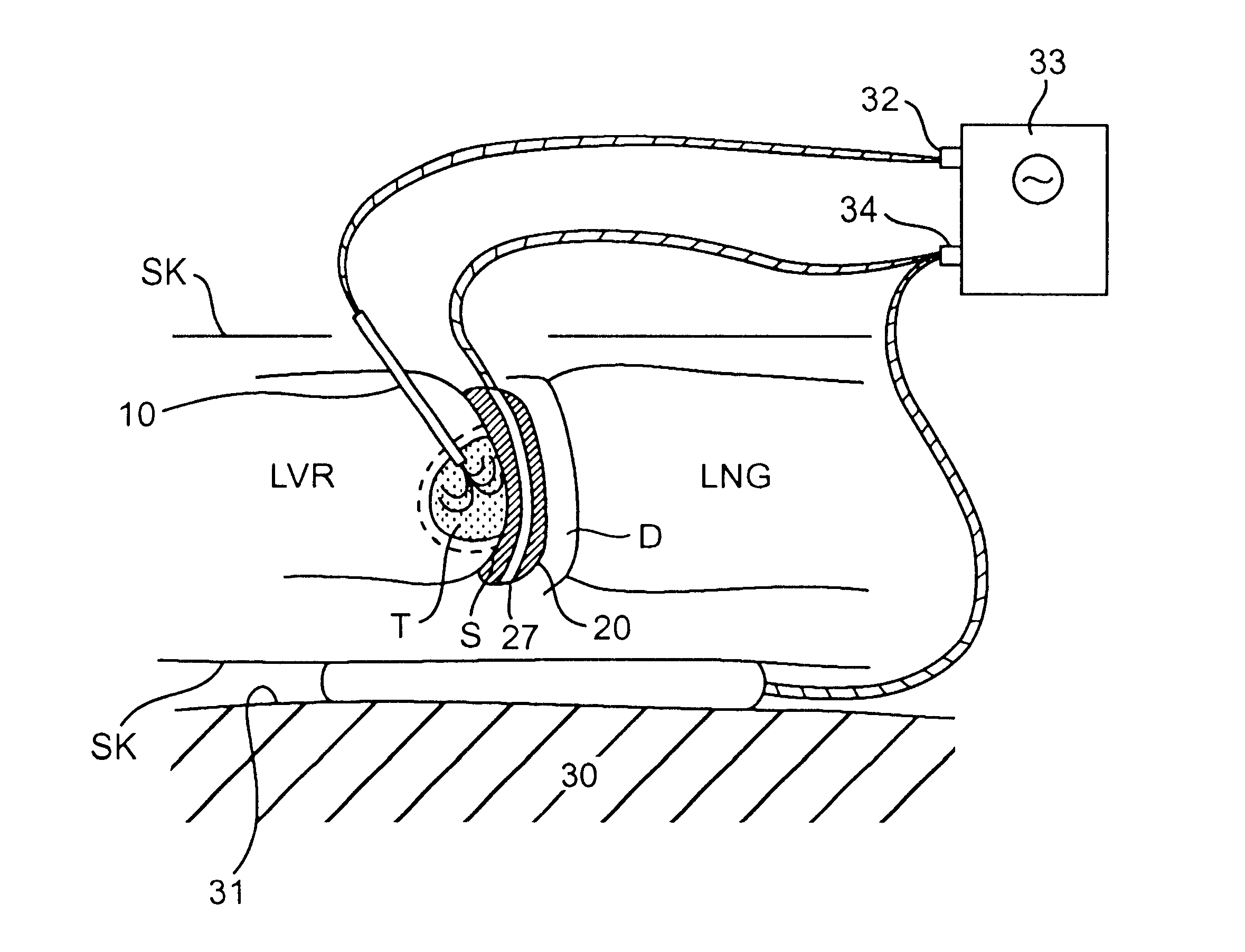
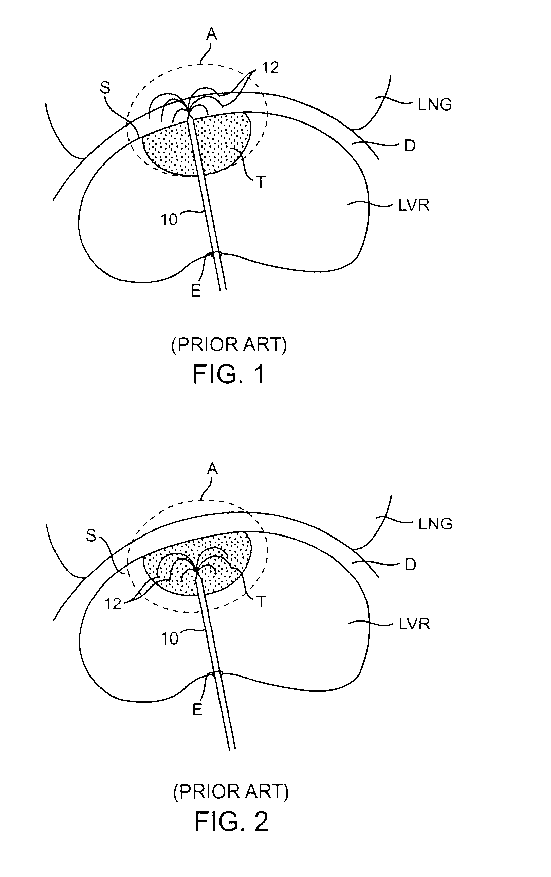
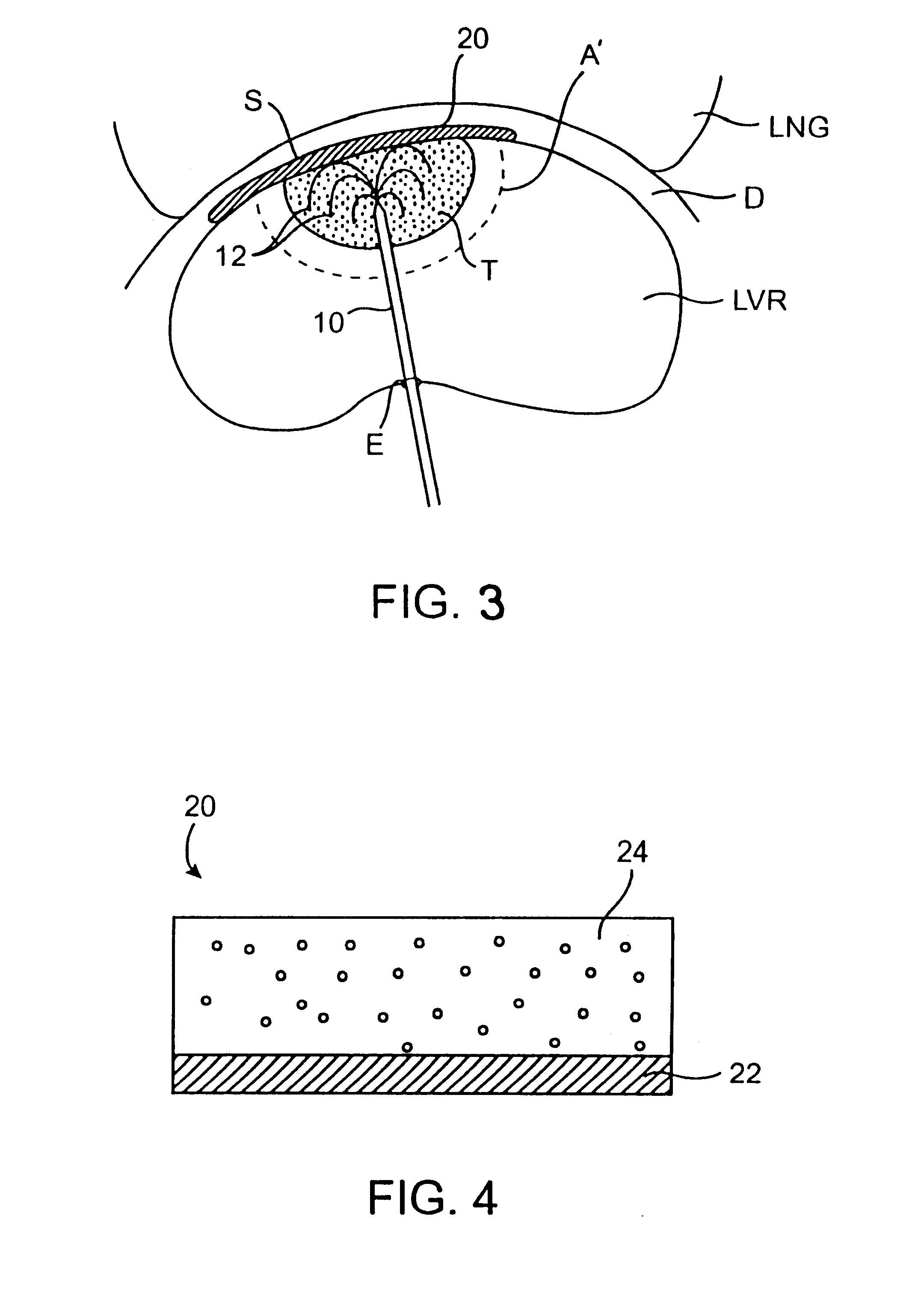
In a first aspect of the present invention, the protective interface shield reduces the incidence of at least one of (a) thermal treatment device penetration into adjacent body tissues and (b)
heat transfer into adjacent non-targeted body tissues. It may be appreciated that the treatment device may include a delivery device, probe or cannula to position the treatment device in a desired location. The shield is comprised of a flexible planar member having at least a first layer comprising a penetration barrier and a second layer comprising a
heat transfer barrier. In the case of electrosurgical treatment, the thermal treatment device may comprise a radiofrequency electrode or
needle electrode. In a preferred embodiment, an array of such electrodes may be advanced forwardly from a distal end of a probe or sharpened cannula during placement, so that the electrodes evert outwardly as they are advanced into the target tissue. The penetration barrier may
resist penetration by the probe and / or needle electrodes as they are advanced and positioned in the target tissue. Specifically, electrode tips may attempt to penetrate the surface of the organ and advance toward adjacent tissue. However, the penetration barrier may serve to
resist tip advancement and / or deflect such a tip in a direction away from the adjacent tissues which are desired to be protected from such treatment. Thus, the penetration barrier may be comprised of any suitable penetration resistant material. Penetration resistance may be measured as
toughness by Charpy or Izod according to ASTM D256. Preferred materials have a penetration resistance or
toughness equal to or greater than 10 cm-kg / cm (2.0 ft-lbf / in).
Placement of a similar dispersive electrode within the interface shield may provide a number of advantages. First, the shape and location of the
lesion created to engulf a tumor or target tissue may be optimized. For example, an asymmetrical lesion may be created to treat a non-spherical tumor or target tissue. Typically, when a dispersive electrode is placed on the patient's
skin, relatively remote from the treatment site, the treatment electrode creates a symmetrical or spherical lesion centered about the electrode. Although the current travels between the treatment electrode and the dispersive electrode, distance between the electrodes disperses the current and creates asymmetrical lesion. By utilizing an interface shield having dispersive electrode layer, the treatment current will preferentially travel between the treatment electrode and the close proximity electrode layer within the shield. The resulting lesion will extend toward the shield and will be ellipsoidal or cylindrical, rather than spherical. In some cases, the dispersive electrode layer may eliminate the need for an external dispersive electrode placed on the patient's
skin. Second, use of a shield containing a dispersive electrode in combination with one or more standard
skin placed dispersive electrodes may result in a higher proportion of the electrical output used to heat tissue in the target region and less energy dissipated into surrounding non-target tissue. Here the dispersive electrode layer, when connected to a
current source in parallel with a dispersive electrode on the surface of the body of the patient, may reduce the
total impedance of the
system so that a higher proportion of the electrical output becomes
usable to heat the target tissue.
The materials comprising the above described functions may be arranged in a number of patterns or configurations to comprise the protective interface shield. Such arrangements may include stacked
layers or encapsulated
layers, to name a few. It is preferred that material comprising a
heat transfer barrier, as described above, be positioned as a layer between the dispersive electrode layer and the surrounding non-target tissue. Typically, materials which provide a barrier to heat transfer also provide electrical insulation. Thus, such a layer may act to further protect the shielded tissue from both damage due to conducted heat and damage due to radiofrequency current heating. It is preferred that material comprising a dispersive electrode layer, as described above, also be positioned as a layer between the heat transfer barrier and the penetration barrier, both of which being non-conductive will isolate the dispersive electrode from direct tissue contact. Such a shield will typically be positioned in the body so that the above described
layers are placed in the following order from the target tissue outward toward the adjacent non-target tissue: penetration barrier, dispersive electrode layer, heat transfer barrier. This may protect the dispersive electrode layer from the possibility of penetration or contact by the treatment electrode placed within the target tissue, and may simultaneously protect the adjacent non-target tissue from excessive
thermal damage. A conductive layer, described previously, may also be present between the penetration barrier and target tissue or fully encapsulating the shield, however it is not essential in this configuration.
In addition, it may be appreciated that multiple interface shields may be used during treatment of a target tissue. It may be desired to position one shield over the surface of the target tissue to protect adjacent tissue. At the same time, shields may also be positioned over tissues that are not immediately adjacent the surface of the target tissue but are within an area of the target tissue that may be injured from the thermal treatment. This may provided added protection for surrounding tissues, specifically particularly susceptible or sensitive tissues. Such individual shields may have an area in the range from 50 cm.sup.2 to 300 cm.sup.2. It is also possible to use more than one shield in any given location, such as in a stacked configuration, to provide possibly additional protective effects, or by
interlocking with adjacent shields to protect additional contiguous tissue area.


