Position sensor and circuit for optical encoder

Inactive Publication Date: 2003-03-04
BISHOP INNOVATION PTY LTD
View PDF2 Cites 32 Cited by
  • Summary
  • Abstract
  • Description
  • Claims
  • Application Information

AI Technical Summary

Benefits of technology

The present invention consists in an electronic circuit comprising a longitudinally disposed array of electromagnetic radiation (EMR) detectors, two or more correlator units, and a phase angle computing unit, the circuit enabling measurement of the relative position of a spatially periodic intensity pattern of incident EMR impinging on the array of detectors, characterised in that the pitch of the array of EMR detectors is arranged to be smaller than the pitch of the spatially periodic intensity pattern of incident EMR, each correlator unit comprises an array of capacitors connected to a buffer, each detector has an output dependent on the incident EMR impinging on that detector, the output communicated to respective one or more capacitors in each of the two or more correlator units, the capacitances of the one or more capacitors determine a correlator coefficient for that detector in

Problems solved by technology

The disadvantage of these systems are, that in order to provide measurement accuracy in the order of microns, very high quality components, "micron accuracy" mechanical and assembly tolerances, and high quality markings are needed.
As an example, in both the above prior art patents, the p

Method used


Image

  • Position sensor and circuit for optical encoder
  • Position sensor and circuit for optical encoder
  • Position sensor and circuit for optical encoder

Examples


Embodiment Construction

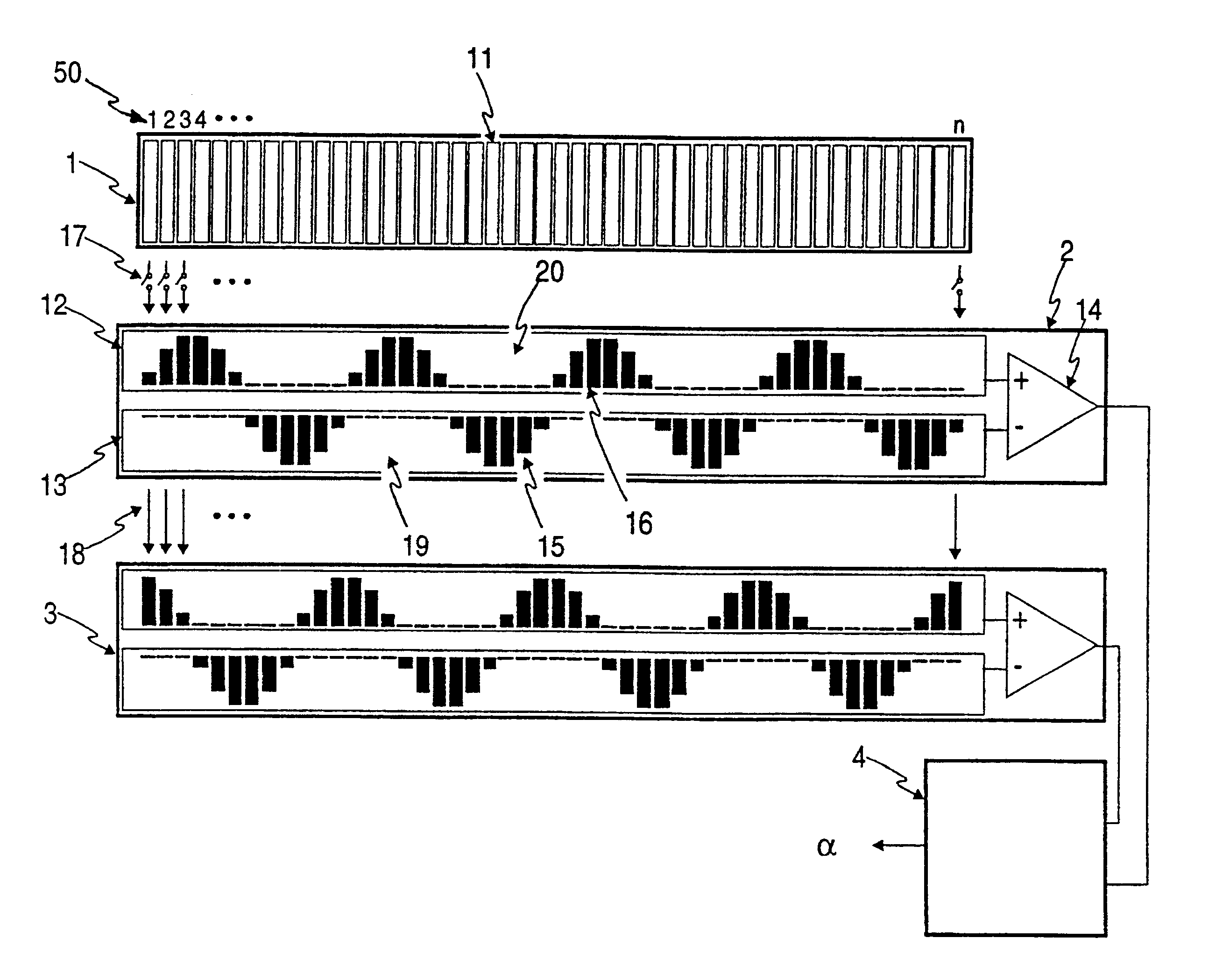
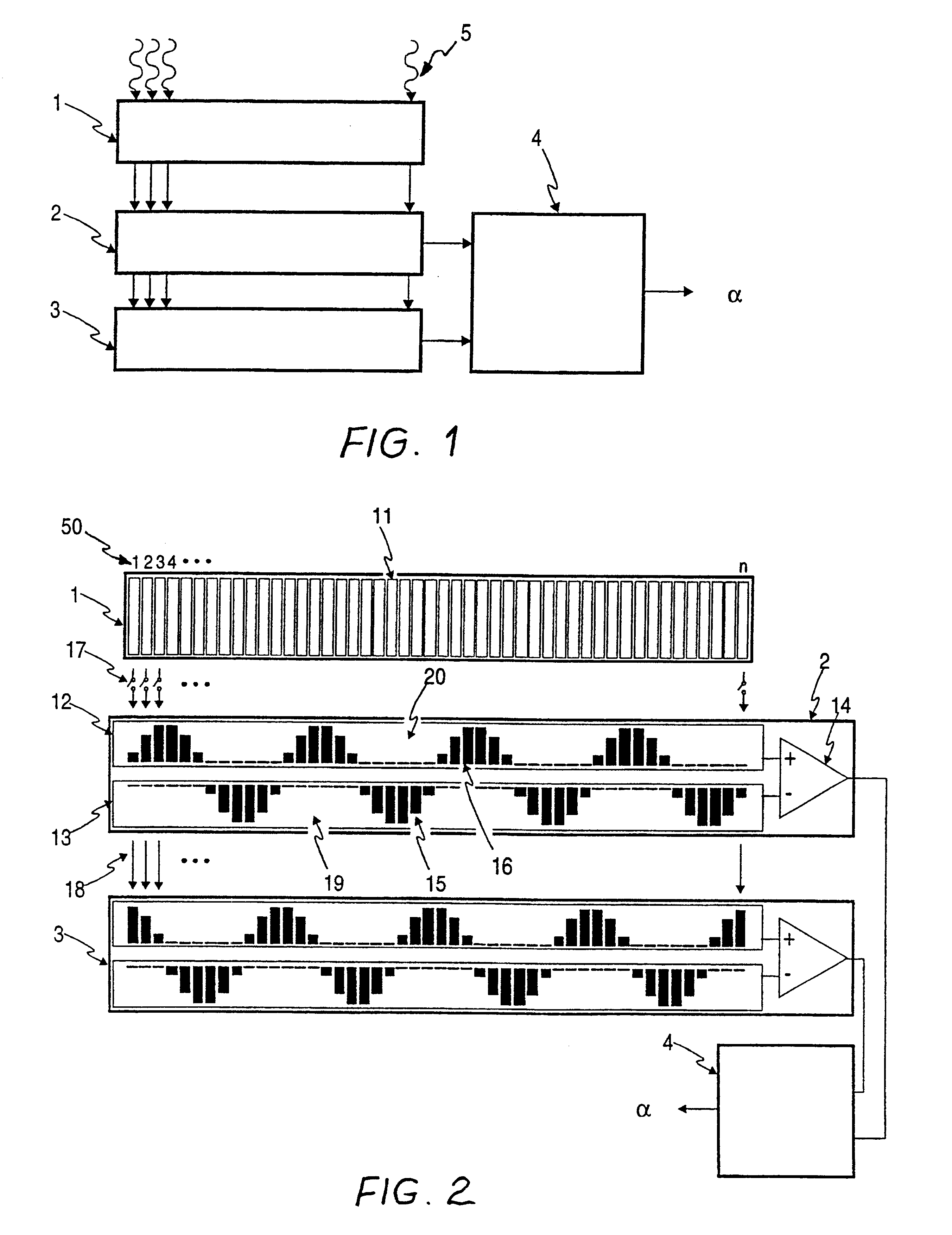
Referring to FIGS. 1 and 2, the electronic circuit is shown in the form of an application specific integrated circuit (ASIC) and comprises array 1 of EMR detectors, sine correlator unit 2, cosine correlator unit 3 and inverse tangent computing unit 4. Array 1 comprises a plurality of identical EMR sensitive photodiode detectors 11, which each have an analog voltage output proportional to the intensity of the incident EMR impinging on the respective detector. An "array index" 50 is shown starting from "1" at the left end of array 1 and increasing to "n" at the right end of array 1.

The same array index convention applies to capacitor sub-array 12 of positive capacitors and to capacitor sub-array 13 of negative capacitors of both sine correlator unit 2 and cosine correlator unit 3. Buffers 14 of each correlator unit buffer the output of the respective capacitor subarrays 12 and 13 with unity voltage gain. Capacitor sub-array 12 of each correlator unit comprises positive common plate 20...


PUM


Abstract

An electronic circuit for measuring the position of a spatially periodic intensity pattern of incident radiation includes an array of detectors (1); two or more correlator units (2, 3) each having arrays of capacitors (12, 13) connected to a buffer (14); and a phase angle computing unit (4). The pitch of the array of detectors (1) is smaller than the pitch of the incident intensity pattern so that the latter is oversampled, yielding high accuracy. The detector outputs (17) are weighted by respective fixed capacitance values (15, 16) which vary periodically along arrays of capacitors (12, 13), and a weighted sum of outputs for each correlator unit (2, 3) is output at its respective buffer (14). The capacitance values (15, 16) of respective correlator units (2, 3) are mutually offset by a predetermined phase shift. The analog computation using capacitor arrays (12, 13) is fast and energy efficient, and can be implemented as a VLSI circuit.

Description

This invention relates to electronic circuits, and in particular to opto-electronic circuits forming part of the sensor component in linear or rotary encoders for the measurement of linear or angular displacement respectively.Typically in such encoders, one or more fixed sources of electromagnetic radiation (EMR) are arranged to illuminate a graduated planar or cylindrical surface. The markings on the graduated surface comprise regions of high and low reflectivity (or, alternatively, high and low transmissibility) to the EMR and the reflected (or transmitted) component of the EMR is arranged to impinge on a fixed opto-electronic sensor which detects the time-dependent or spatially distributed intensity pattern of the incident EMR, and hence provide measurement of the relative position of the graduated surface. Both such "reflective" and "transmissive" encoder versions are used commonly in industry and consumer products today for measurement of linear or angular displacement, althoug...

Claims


Application Information

Patent Timeline
IPC IPC(8): G01D5/12G01D5/24G06G7/00G06G7/22G01B11/00G01D5/30G01D5/34G01D5/36G06G7/19G06K7/10
CPCG06G7/22G01D5/24G01J1/4228G01D5/2454G06K7/10237G01J2001/4233
Inventor MORTARA, ALESSANDROMASA, PETERHEIM, PASCALHEITGER, FRIEDRICH
Owner BISHOP INNOVATION PTY LTD
Why Eureka
Try Eureka