Method of continuous cationic living polymerization

a cationic living and polymerization technology, applied in the field of continuous cationic living polymerization, can solve the problems of inferior uniformity in molecular weight, unsatisfactory uniformity, and the inability to achieve uniformity, so as to improve the mixing and heat removal capacity, reduce the energy load, and improve the mixing and heat removal

Inactive Publication Date: 2003-08-05
KANEKA CORP
View PDF9 Cites 20 Cited by
  • Summary
  • Abstract
  • Description
  • Claims
  • Application Information

AI Technical Summary

Benefits of technology

feeding a reaction solution from said flow-through stirring vessel reactor to a flow-through tubular reactor continuously to thereby allow the living polymerization to proceed,
in the formula, R.sup.4 represents a hydrogen or a saturated hydrocarbon group containing 1 to 18 carbon atoms, B represents a divalent hydrocarbon group containing 1 to 30 carbon atoms and G represents a univalent substituent. The isobutylene polymer obtained by this method and terminally having a protected hydroxyl group can be easily transformed to the corresponding isobutylene polymer terminally having a hydroxy group by deprotection.
In accordance with the invention, the reaction solution discharged from the first flow-through stirring vessel reactor is led to a flow-through tubular reactor for continued polymerization reaction. The structure of the tubular reactor is not particularly restricted but one having the ability to remove heat is preferred. Thus, for example, a double tubular type or shell and tube type can suitably be used. For improving the mixing and heat-removing capacity, it is also possible to use a tubular reactor with one or more static mixing structures comprising a number of mixing elements incorporated therein. As the static mixing structure, there may be mentioned, for example, well-known static mixers, such as of the Sulzer, Koenigs, Toray or Noritake Company type, and the like. The number of mixing element is preferably not less than 3. It is preferred for the tubular reactor to be used in the practice of the invention to have good mixing property in the radial direction of the tube, which is suited for heat transfer and for mixing of the components fed, and have no propensity to cause a reaction solution residence time distribution in the lengthwise direction of the tube.
Since the polymerization procedure is carried out in a continuous flow-through mode in the cationic living polymerization according to the invention, the feeding of respective raw materials to the reactor and the discharge of the reaction solution can be conducted continuously at a constant flow rate. Therefore, in the practice of the invention, it is preferred to recover the sensible heat of the reaction solution to reduce the energy load by subjecting the reaction solution continuously discharged from the reactor to heat exchange with at least one of the raw material solutions to be fed to the reactor. In particular, the cationic living polymerization proceeds in many instances at low temperatures within the range of -30.degree. C. to -100.degree. C., so that the load on the refrigerating machine for cooling the raw material solutions is great. Therefore, by utilizing the low-temperature reaction solution discharged from the reactor for cooling the raw material solution via a heat exchanger, efficient production is made possible. The heat exchanger which can be used is not particularly restricted but, for example, the double tubular, shell and tube, plate, spiral and other types may be used. By applying the so-called countercurrent heat exchange process which comprises causing heat exchange between the low-temperature reaction solution flowing through the heat exchanger with the temperature thereof gradually rising and the raw material solution before cooling and leading the same gradually to the low-temperature side, it is possible to cool the raw material solution to a temperature level close to the low-temperature reaction solution.

Problems solved by technology
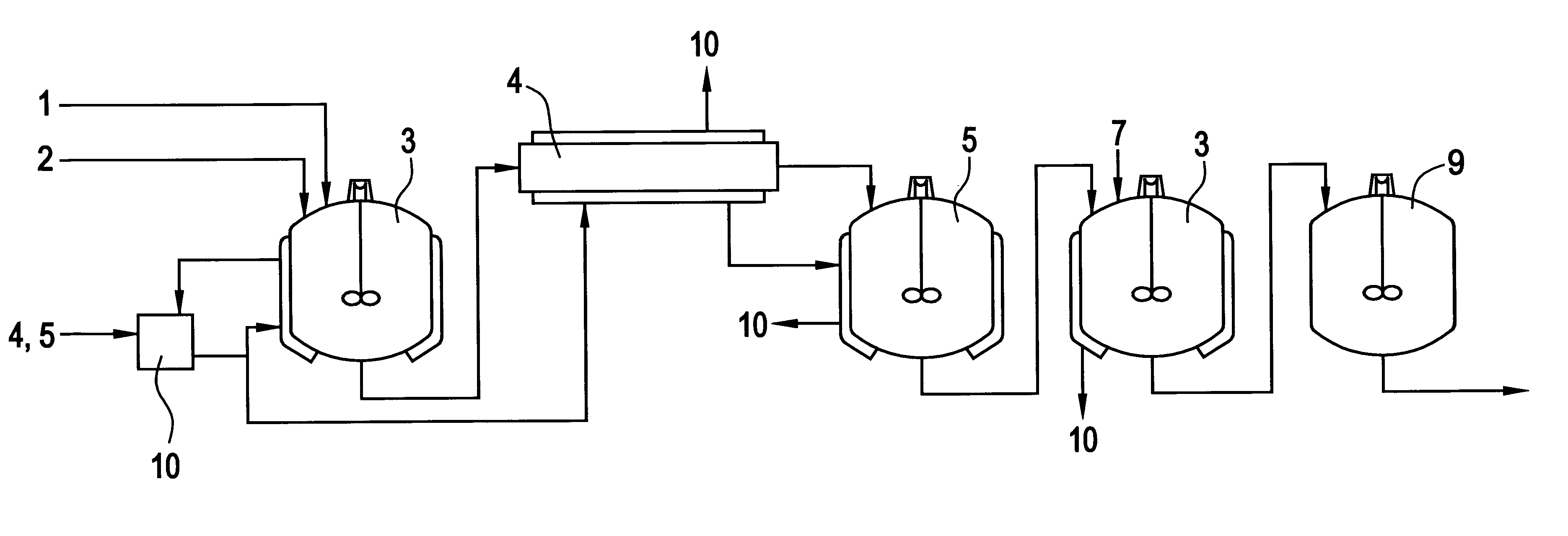
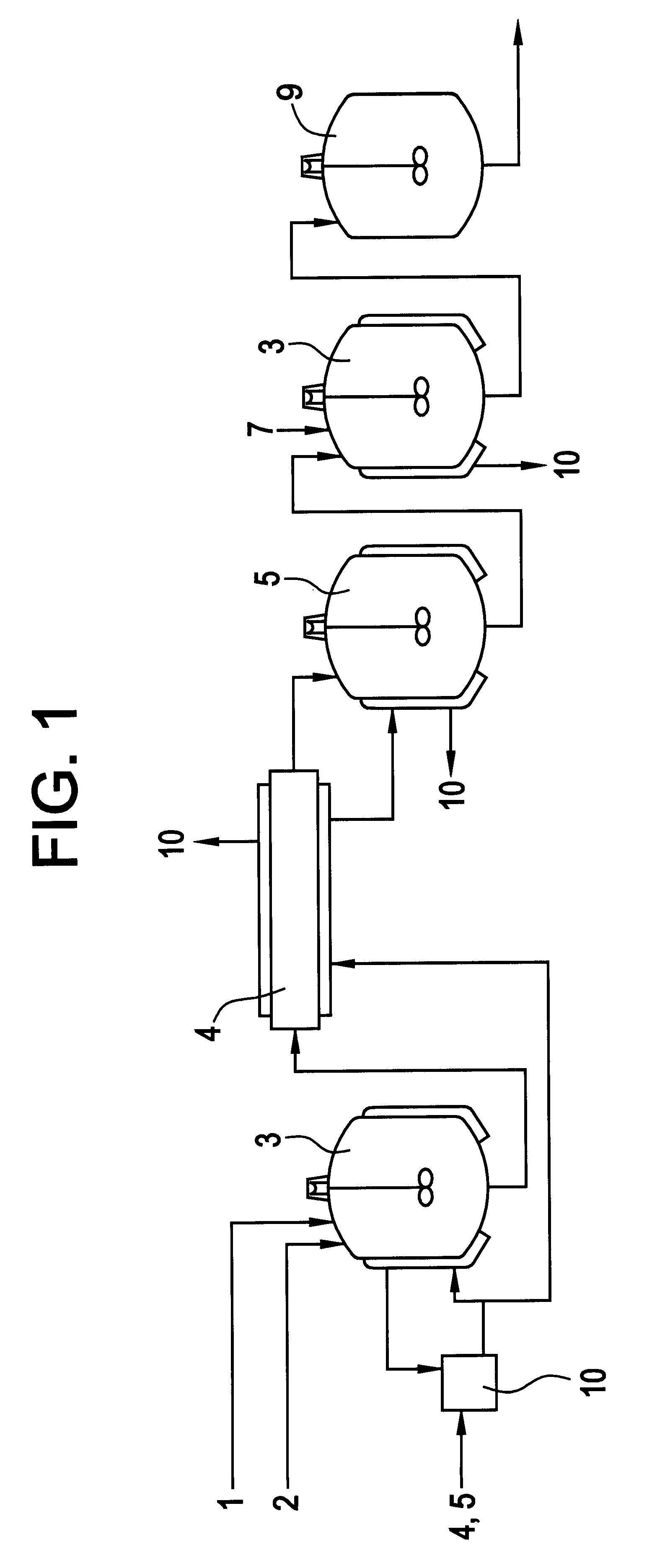
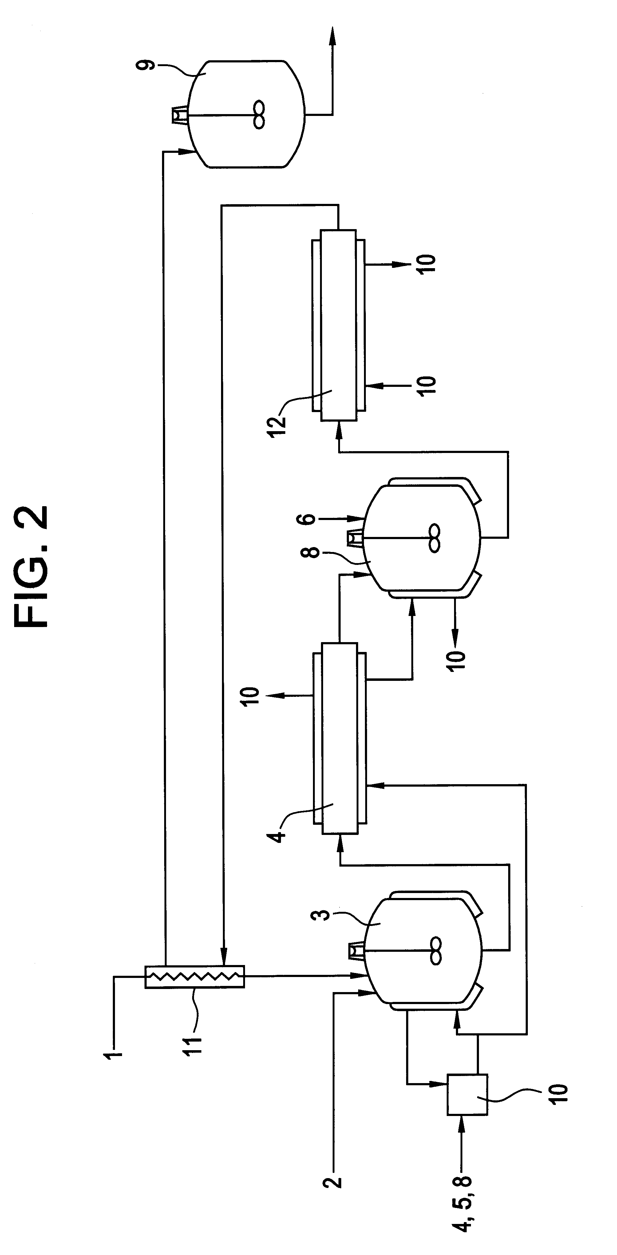
However, there still remain some problems in employing the continuous polymerization process for improving the productivity.
However, the uniformity in molecular weight is inferior as compared with the batchwise polymerization process.
In a report on anionic living polymerization (Japanese Kokai Publication Hei-11-286520), polymers with a molecular weight distribution of 1.3 to 1.8 are obtained using a flow-through tubular reactor and, although the molecular weight distribution is rather smaller as compared with cationic living polymerization, the uniformity is not yet satisfactory.
It is considered that when these tubular reactors were used, the mixing just after feeding of the raw materials to the reactor was insufficient and, as a result, the reaction did not occur adequately but side reactions concurred.
As discussed above, when cationic living polymerization is carried out by the continuous flow-through process, the residence time distribution of the reaction solution becomes wide and non-initiator-derived polymers are formed by side reactions and, consequently, a problem arises that the distribution of the polymer obtained becomes high.
As the distribution increases, the Mw increases and, in many cases, the viscosity of the polymer increases, making the polymer difficult to handle.
Another problem is that side reactions occur and, as a result, the functional group introduction is not effected as designed.
The functional groups introduced into a polymer are to be involved in a crosslinking or some other reactions and, therefore, if the functional group introduction is not effected as designed, it is impossible in many cases to obtain satisfactory products.
Those are important problems characteristic of the continuous operation.

Method used


Image

  • Method of continuous cationic living polymerization
  • Method of continuous cationic living polymerization
  • Method of continuous cationic living polymerization

Examples


example 1

The experimental apparatus used in Examples 1, 3 and 5 and Comparative Examples 1, 2, 3 and 4 is shown in FIG. 3.

A storage tank 21 (capacity 2,500 ml), a storage tank 22 (capacity 2,500 ml) and a stirring vessel reactor 25 (capacity 1,200 ml, large-sized paddle blade, d / D=0.5, 3 baffle plates) and a tubular reactor 26 (capacity 2,000 ml, inside diameter 10 mm) were purged with nitrogen and the storage tanks 21 and 22 and the reactors 25 and 26 were then charged with toluene and ethylcyclohexane in a volume ratio of about 3:1.

Brine was fed to the jacket portion each of the storage tanks 21 and 22 and the reactors 25 and 26 from a refrigerator line 29 to thereby adjust the storage tank and reactor inside temperatures each to -65.degree. C., and the storage tank 21 was charged with a polymerizable monomer and a polymerization initiator and the storage tank 22 with a catalyst and an electron donor. Isobutylene was used as the polymerizable monomer, 1,4-bis(.alpha.-chloroisopropyl)benzen...

example 2

The experimental apparatus used in Examples 2 and 4 is shown in FIG. 4.

The reaction solution at the outlet of the tubular reactor 26 as obtained by the same procedure as in Example 1 was once allowed to reside in a cushioning vessel 30 and, then in the stirring vessel reactor 35, reacted with allyltrimethylsilane, an end capping agent, added in an amount of 3 moles per mole of p-DCC, batchwise at a temperature of -65.degree. C. for 2 hours. The reaction solution was mixed with water for catalyst deactivation and washed with water and the solvent was then removed to give an allyl-terminated isobutylene polymer. The terminal structure was determined by measuring the resonance signals for the protons assignable to the respective structures by .sup.1 H-NMR (300 MHz) and comparing the data. The analytical data for the polymer obtained were as shown in Table 4. The conversion rate of the monomer component on the occasion of feeding the reaction solution from the reactor 25 to the reactor ...

example 3

An experiment was carried out according to the same procedure as in Example 1 except that the amount of (.alpha.-picoline was 6.3 ml. The difference between the reaction solution temperature in the reactor 25 and the jacket temperature and the analytical data for the polymer at the reactor outlet were as shown in Table 5. The conversion rate of the monomer component on the occasion of feeding the reaction solution from the reactor 25 to the reactor 26 was 50% by weight.


PUM

PropertyMeasurementUnit
mole ratioaaaaaaaaaa
molecular weight distributionaaaaaaaaaa

Abstract

A polymer is produced by feeding a polymerization initiator, a cationically polymerizable monomer component and a catalyst continuously to a flow-through stirring vessel reactor to thereby allow the living polymerization to initiate and feeding a reaction solution from said flow-through stirring vessel reactor to a flow-through tubular reactor continuously to thereby allow the living polymerization to proceed, said reaction solution having a conversion rate of said cationically polymerizable monomer component of not less than 1% by weight to less than 90% by weight.

Description

The present invention relates to a method of continuous cationic living polymerization. More particularly, it relates to a method comprising continuously feeding raw materials to thereby cause the polymerization reaction to proceed and continuously discharging the product.Living polymerization is a mode of polymerization in which the polymerization reaction initiated at a starting point(s) on an initiator can proceed without being disturbed by such side reactions as termination and chain transfer reactions and thus allows the molecular chain to grow. If, in such living polymerization, the polymerization reactions from all initiation sites are started simultaneously, a polymer uniform in molecular weight can be obtained and, further, it is possible to introduce a specific functional group terminally or otherwise into the polymer or synthesize a block copolymer by adding a different monomer species near the end point of the polymerization reaction. According to the monomer species to ...

Claims


Application Information

Patent Timeline
Patent Type & Authority Patents(United States)
IPC IPC(8): C08F10/00C08F10/10C08F297/00C08F2/00C08F110/10C08F110/00C08F210/00C08F210/10C08F2/01C08F2/06C08F4/00
CPCC08F2/00C08F10/10C08F297/00C08F2/38C08F4/00C08F4/06C08F2/01C08F110/10C08F210/10C08F2500/03C08F212/08
Inventor TERAZAWA, HIROMUWACHI, SHUNFURUKAWA, NAOKI
Owner KANEKA CORP
Why Eureka
Try Eureka