

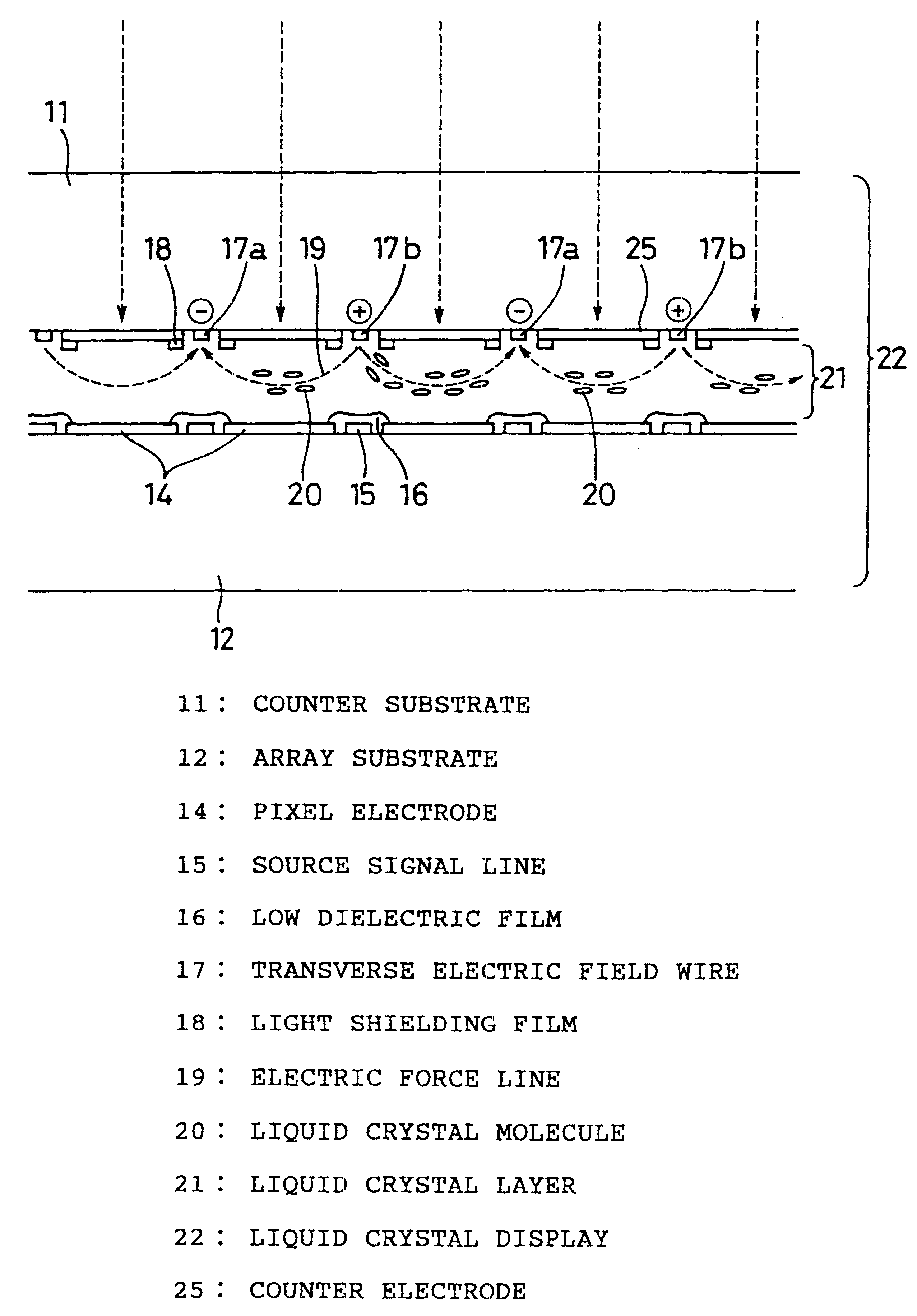
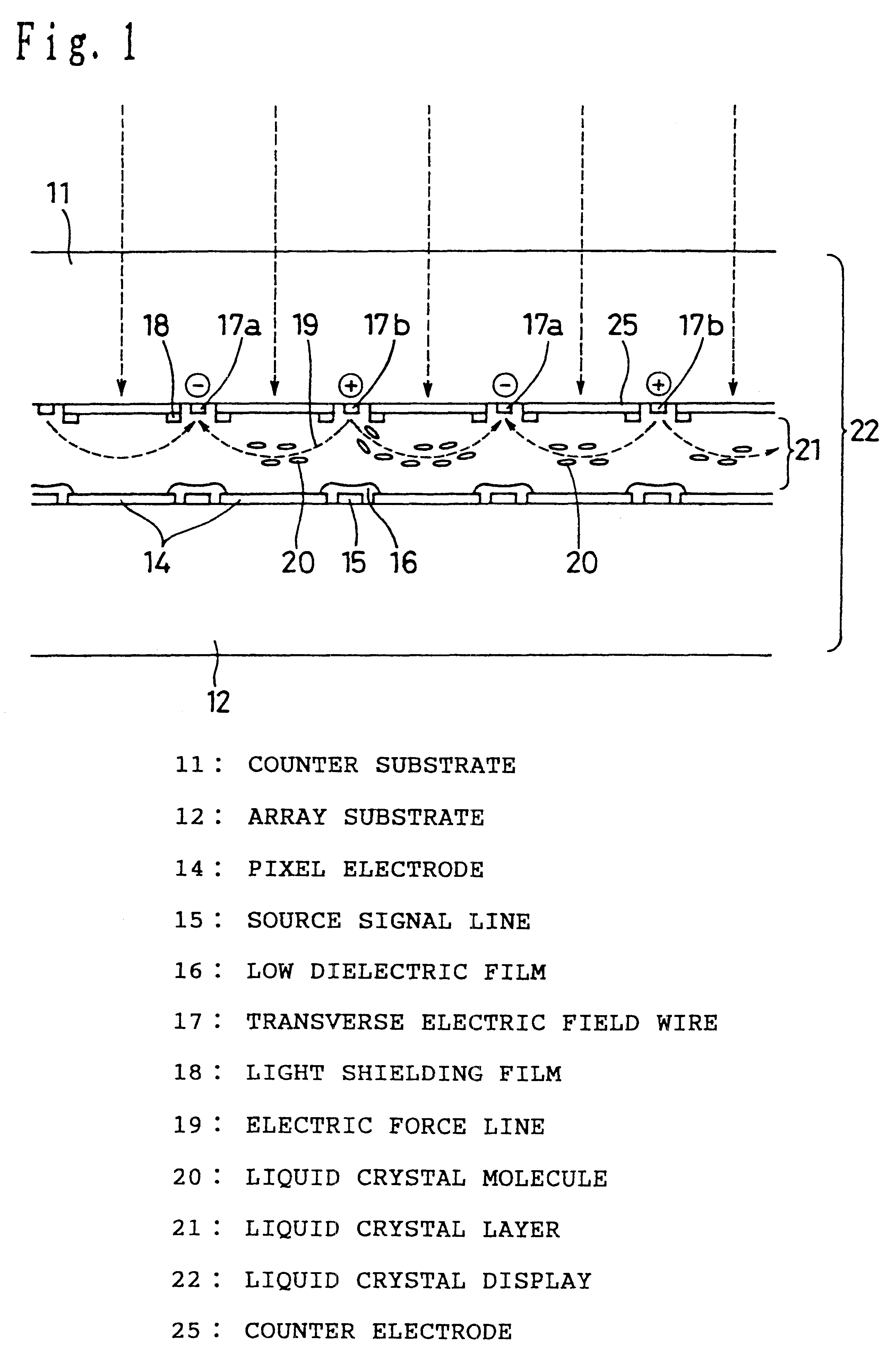
Liquid crystal display panel including a light shielding film to control incident light
a liquid crystal display panel and incident light technology, applied in the field of display panels, can solve the problems of poor light utilization efficiency of conventional units such as the aforementioned, manufacturing defects, and inability to realize high brightness displays
- Summary
- Abstract
- Description
- Claims
- Application Information
AI Technical Summary
Benefits of technology
Problems solved by technology
Method used
Image

Examples
first embodiment
A description will hereinafter be made of an embodiment of a projection type display of the present invention in reference to the drawings. The constitution of a projection type display in the present invention is shown in FIG. 141. 1411 is a light source as light generation means, 1412 a color purity enhancement filter, and 1415 a projection lens as projection means.
The light source 1411 is constituted by a discharge lamp 1411a, a concave mirror 1411b, an ultraviolet-ray and infrared-ray (UVIR) cut filter 1411c. The discharge lamp 1411a is constituted by a metal halide lamp, and dysprosium (Dy) and neodymium (Nd) are enclosed within the light emitting tube. The emission spectrum is shown in FIG. 147. As evident in FIG. 147, in the spectral distribution of light emitted by the metal halide lamp, a great number of continuous emission spectra by dysprosium (Dy) and neodymium (Nd) and a bright line spectrum by mercury are present together. The concave mirror 1411b is formed with glass ...
second embodiment
Furthermore, as in the second embodiment, in the case where the difference in refractive index between a high refractive index layer and a low refractive index layer is small, if the absolute value of reflectance at a peak wavelength is attempted to be made high, there will be a need to increase the number of dielectric multilayer films, and depending on the number of films, there will be the fear that a crack will occur. In this case, the high refractive index layer can be constituted by a combination of TiO.sub.2 and ZnS whose refractive indexes are nearly the same and which has the property that the directions of internal stresses cancel out each other. The refractive indexes of the TiO.sub.2 and ZnS layers are nearly 2.30. In the TiO.sub.2 layer, tensile stress is produced, and in the ZnS layer, compression stress is produced. Therefore, for example, if the layers in the high refractive index multilayer film are respectively constituted by three layers consisting of TiO.sub.2, Z...
PUM
| Property | Measurement | Unit |
|---|---|---|
| thickness | aaaaa | aaaaa |
| luminance | aaaaa | aaaaa |
| brightness | aaaaa | aaaaa |
Abstract
Description
Claims
Application Information