Method of reinforcing catalyst reaction

Inactive Publication Date: 2003-10-14
TAS PROJECT
View PDF7 Cites 14 Cited by
  • Summary
  • Abstract
  • Description
  • Claims
  • Application Information

AI Technical Summary

Benefits of technology

The present invention aims at combining the prior art technologies of magnetic activation of a fluid and optical catalyst process to overcome the drawbacks of both technologies. Specifically, the present invention provides a method of enhancing the catalytic reaction of a semiconductor which is capable of making maximum use of the catalyst power of the semiconductor and

Problems solved by technology

However, the effect and reaction of these techniques, when applied individually, have been insufficient and can last for only a short period of time.
Large scale commercialization of this technique has been hindered by such hurdles as various factors that hamper the efficient transm

Method used


Image

  • Method of reinforcing catalyst reaction
  • Method of reinforcing catalyst reaction
  • Method of reinforcing catalyst reaction

Examples


examples 1 to 3

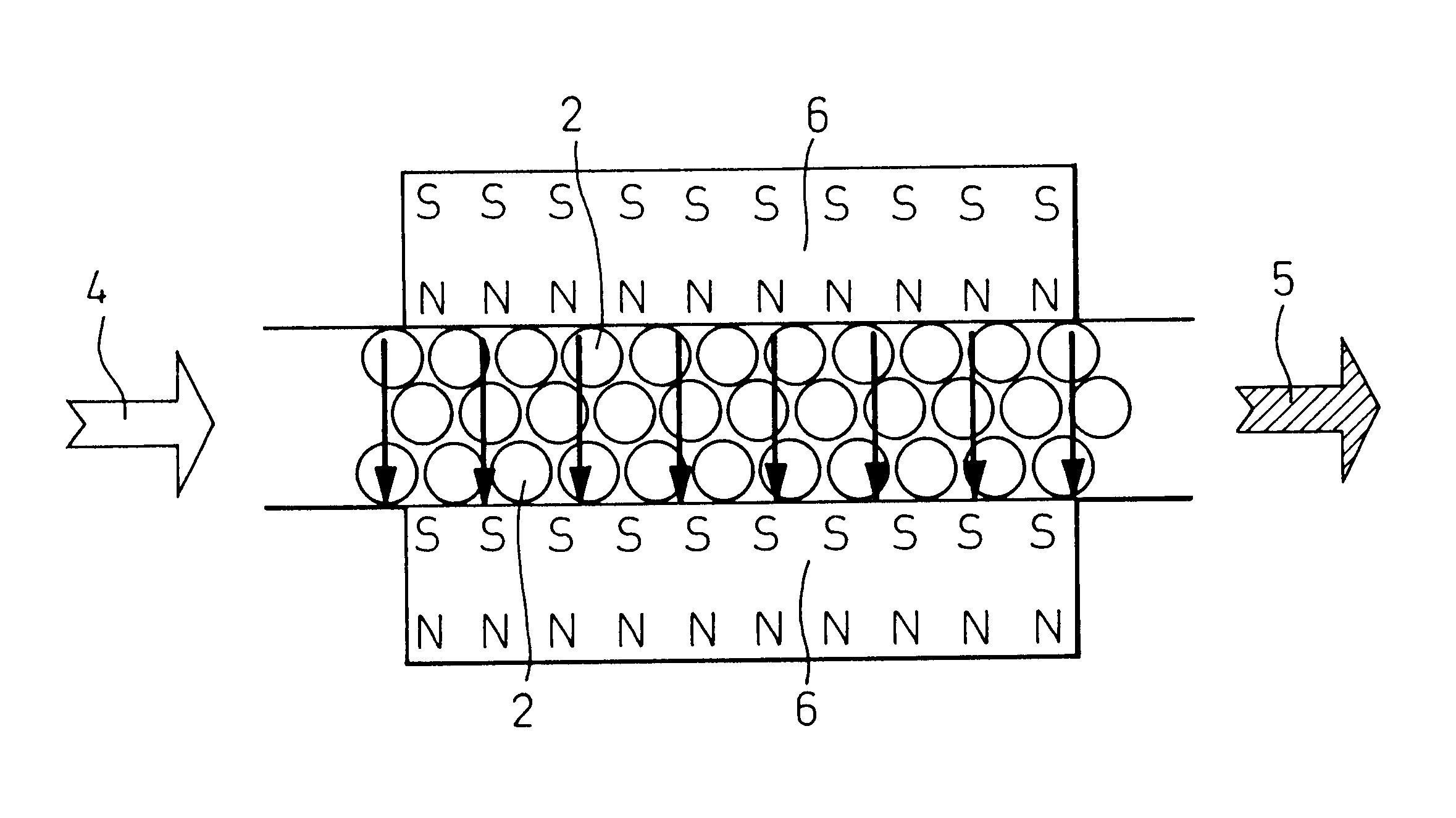
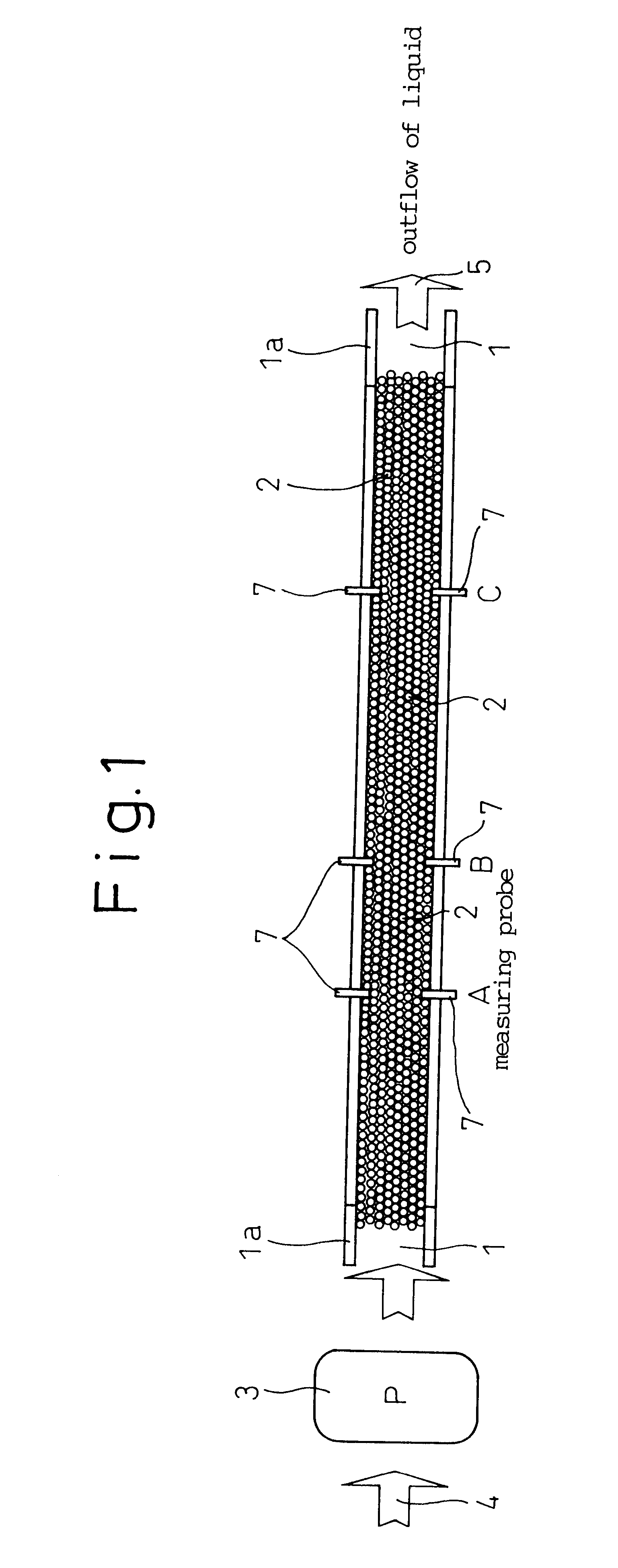
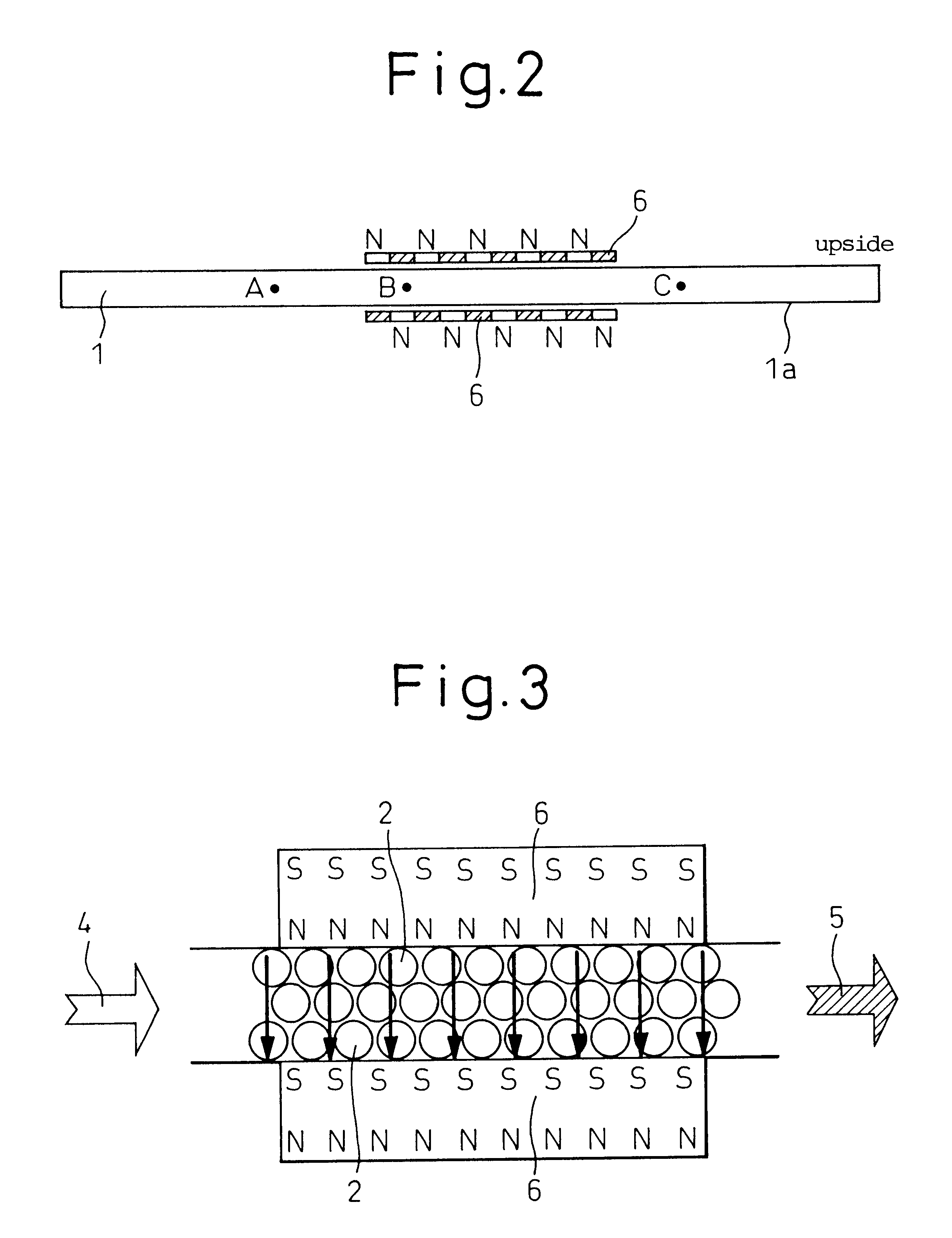
are examples of arranging neodymium magnets (Nd-Fe-B magnets) having surface magnetic flux density of 4,000 Gauss so as to surround a fluid passage which is filled with a semiconductor catalyst in the form of titanium dioxide particles, while a stock solution is sent through the fluid passage under pressure to activate the stock solution through oxidizing and reducing reactions of the titanium dioxide, thereby purifying the stock solution.

In FIGS. 1 and 2, the reference numeral 1 denotes a passage for passing the stock solution, 1a denotes a stainless pipe which forms the fluid passage and is 37 mm wide, 15 mm high and 1,000 mm long with wall thickness of 1.5 mm. The reference numeral 2 denotes titanium dioxide pellets which are an oxide semiconductor, 3 denotes a pump which forces the stock solution 4 to flow through the fluid passage at a low flow rate of 1.9 liters / min. or a high flow rate of 5.4 liters / min., 4 denotes the stock solution to be processed, 5 denotes outflow of a li...

example 1

Denitration Reaction Using Magnetic Field Catalyst

Denitration reaction is verified by measuring the concentrations of nitrous acid and nitric ion in the processed liquid 5 after the magnetic field catalyst processing in cases A, B and C, using the apparatus shown in FIGS. 1, 2 and sodium nitrate solution as the stock solution 4.

1. Sodium nitrate solution having concentration of 10 mg / liter (10 ppm) (maximum permissible concentration for water quality of public water works) is prepared as the stock solution 4.

2. An experimental system similar to that of the test shown in Tables 1-1 and 1-2 is used to measure the nitric acid ion concentration in the processed liquid after the magnetic field catalyst processing by means of high performance liquid chromatography (HPLC), with the specimen being separated, caused to undergo grease reaction and finally quantitatively determined by means of the intensity of color developed through a diazo reaction. In the following description, NOx concentr...

case b

rea of NOx when processed in a system which is not provided with magnets


PUM

PropertyMeasurementUnit
Magnetic fieldaaaaaaaaaa
Fractionaaaaaaaaaa
Fractionaaaaaaaaaa

Abstract

A method is provided for enhancing the catalytic reaction, by disposing a semiconductor catalyst in a fluid which includes charged particles and generating a magnetic field in the space where the semiconductor catalyst is disposed so as to impart electromagnetic induction energy to the charged particles. This method is capable of carrying out the reduction of nitrogen oxides, dechlorination of organic chlorine compounds and other reactions efficiently.</PTEXT>

Description

The present invention relates to a method of enhancing a catalytic reaction and, more particularly, to a technique for a magnetic field catalyst process which utilizes magnetic field and charged particles to enhance catalytic reactions such as oxidation, reduction, denitrification, desulfurization and dechlorination by means of a semiconductor catalyst. This technology is useful for efficiently and economically processing chemical substances dissolved in gases or water in a large scale through such reactions as oxidation and. reduction, and is applicable specifically to chemical plants, remedial operation for environmental pollution, water purification, deodorization, air purification and agricultural / livestock farms.A technology to activate or reform a fluid (gas or liquid) by applying a magnetic field to the gas or liquid has been known in the prior art. A technology is also widely known by which a semiconductor catalyst such as titanium oxide is irradiated with ultraviolet radiat...

Claims


Application Information

Patent Timeline
IPC IPC(8): B01J19/08B01J19/10B01J19/24B01D53/86B01J37/00B01J37/34C02F1/72C02F1/36C02F1/34C02F1/48
CPCB01D53/8662B01J19/087B01J19/10B01J19/2415B01J37/34C02F1/36C02F1/48C02F1/725C02F2101/36B01J2219/00099B01J2219/00139B01J2219/00177B01J2219/0852B01J2219/0854B01J2219/0862B01J2219/0877C02F1/481C02F2101/16B01D2259/814Y02W10/33B01D53/8628B01J21/063B01J37/342B01J2219/085B01J2219/0892
Inventor TAKAKI, ATSUSHI
Owner TAS PROJECT
Why Eureka
Try Eureka