Spiral reverse osmosis membrane element, reverse osmosis membrane module using it, device and method for reverse osmosis separation incorporating the module

Inactive Publication Date: 2003-12-02
TORAY IND INC
View PDF16 Cites 59 Cited by
  • Summary
  • Abstract
  • Description
  • Claims
  • Application Information

AI Technical Summary

Benefits of technology

An object of the present invention is to provide a spiral reverse osmosis membrane element which can suppress lowering of the performance caused by concentration polarization on the reverse

Problems solved by technology

There is a critical problem in operating the element such that the element performance lowers due to concentration polarization.
For this reason, the reverse osmosis membrane cannot develop its capability and the performance of the element lowers.
With the feed liquid passage member 4 having a smaller thickness, however, the passage defined by the feed liquid passage member 4 is easily clogged with fouling substances contained in the feed liquid such as impurities and microorganisms.
As a result, the element performance lowers and the pressure loss in the feed liquid increases.
To keep up the quality and quantity of permeated liquid, the operating pressure for the feed liquid needs to be raised, and hence a high-pressure pump requiring electric power to operate and pressure pipes must be provided, resulting in increased liquid production costs.
However, there is a problem that the pressure loss in the feed liquid increases, so that the operation cost and the equipment cost may increase.
Further, the pressure-loss decreasing effect produced is too small to be practical under a flow velocity condition of the feed liquid in the actual operation.
Furthermore, this net member is expensive because it requires an advanced net-making technique.
If it happens, the reverse osmosis membrane may be damaged by an upper edge of

Method used


Image

  • Spiral reverse osmosis membrane element, reverse osmosis membrane module using it, device and method for reverse osmosis separation incorporating the module
  • Spiral reverse osmosis membrane element, reverse osmosis membrane module using it, device and method for reverse osmosis separation incorporating the module
  • Spiral reverse osmosis membrane element, reverse osmosis membrane module using it, device and method for reverse osmosis separation incorporating the module

Examples


Example

Comparative Example 1

(1) Feed Liquid Passage Members

Net members a, b each having a net structure shown in FIG. 3 were prepared. As for the net member a, the average thickness was 0.7 mm, the distance (Y) between the cross-points 7c, 7d was 5 mm, and the angle .alpha. was 33.degree.. As for the net member b, the average thickness was 0.7 mm, the distance (Y) between the cross-points 7c, 7d was 4 mm, and the angle .alpha. was 47.degree..

Each of the net members a, b was arranged on a parallel flat plate cell (passage width: 160 mm, passage length: 300 mm) in a manner that a line connecting the cross-points 7c, 7d extends in parallel with the passage direction. Water of 25.degree. C. in temperature was caused to flow, and the flow velocity on the cell surface and the pressure loss produced between both ends of the cell were measured. The results are shown in FIG. 13.

As apparent from FIG. 13, in the case of the net member a, the pressure loss is very small.

(2) Reverse Osmosis Membrane El...

Example

Comparative Examples 2 to 5

(1) Preparation of Reverse Osmosis Membranes and Feed Liquid Passage Members

A cross-linked aromatic polyamide composite membrane was prepared, which was flat membrane having the performance such that permeated water was obtainable at a rate of 0.85 m.sup.3 / m.sup.2 day and at a salt rejection of 99.75% when a saline solution having a concentration of 3.5% was subjected to reverse osmosis separation, at a pressure of 5.5 MPa. The reverse osmosis separation was implemented by using a flat membrane evaluation cell provided with the composite membrane having an effective membrane area of 32cm.sup.2.
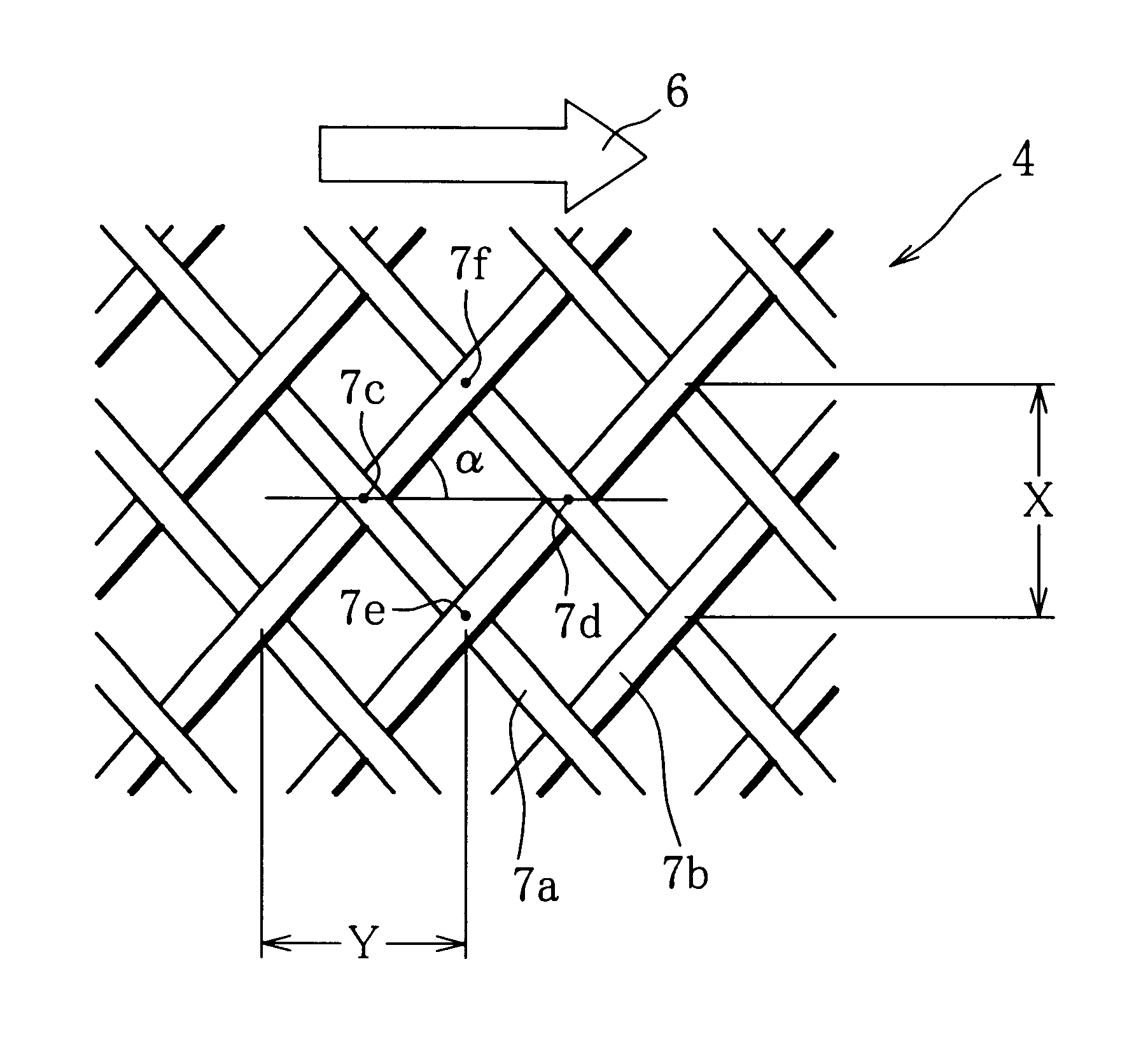
 The above-mentioned composite membrane will be referred to as membrane I.

Another cross-linked aromatic polyamide composite membrane was prepared, which was a flat membrane having the performance such that permeated water was obtainable at a rate of 0.87 m.sup.3 / m.sup.2.multidot.day and at a salt rejection of 99.72% when a saline solution having a concentration of ...

Example

Regarding example 4 and comparative example 5, pressure loss was also measured. The results are shown in table 2.

As apparent from table 2, when the elements of the present invention are used, the water permeate flow increases, the salt rejection increases and the pressure loss much decreases.


PUM

PropertyMeasurementUnit
Lengthaaaaaaaaaa
Thicknessaaaaaaaaaa
Thicknessaaaaaaaaaa

Abstract

A spiral reverse osmosis membrane element of the present invention includes a plurality of bag-shaped reverse osmosis membranes, permeated liquid passage members arranged inside the reverse osmosis membranes, and a plurality of feed liquid passage members interposed between the reverse osmosis membranes, those membranes and passage members being wound around an outer surface of a hollow pipe in a manner that only the interiors of the reverse osmosis membranes communicate with through-holes formed in the surface of the hollow pipe. Each of the feed liquid passage members is a mesh member having series of quadrilateral meshes formed by a plurality of linear members crossing each other. Two opposite cross-points out of four cross-points of each of the quadrilateral meshes are in line in parallel with an axial direction of the hollow pipe. And relations 2 mm<=X<=5 mm and X<=Y<=1.8X are both satisfied where X denotes a distance between the cross-points in a direction perpendicular to the axial direction of the hollow pipe and Y denotes a distance between the cross-points in the axial direction of the hollow pipe.

Description

This application is the national phase under 35 U.S.C. .sctn.371 of PCT International Application No. PCT / JP99 / 03274 which has an International filing date of Jun. 18, 1999, which designated the United States of America.The present invention relates to a spiral reverse osmosis membrane element capable of producing permeated water with a small quantity of input energy at a low operating cost, a high salt rejection and a high water permeation rate or water flow rate when applied to seawater desalination, and relates to a reverse osmosis membrane module using the aforementioned element, a reverse osmosis separation apparatus incorporating therein the module, and a reverse osmosis separation method.A reverse osmosis separation method is a method for obtaining permeated liquid having a low solute concentration by passing a solution through a reverse osmosis membrane at a pressure higher than its osmotic pressure to thereby separate and remove part of a solute. The reverse osmosis separat...

Claims


Application Information

Patent Timeline
IPC IPC(8): B01D63/10B01D63/12B01D61/02B01D65/00
CPCB01D61/022B01D65/00B01D63/12B01D63/10Y02A20/131B01D61/026B01D63/101
Inventor KIHARA, MASAHIROMINEGISHI, SHINICHINAKANISHI, TAKAYUKI
Owner TORAY IND INC
Why Eureka
Try Eureka