Magnetic recording medium and manufacturing method therefore

a technology of magnetic recording medium and manufacturing method, which is applied in the field of magnetic recording medium, can solve the problems of insufficient orientation control of magnetic layer, increased media noise, and insufficient media noise, and achieves the effect of improving crystal orientation and crystallinity of alignment-control, easy production, and simplified manufacturing process

Inactive Publication Date: 2004-01-06
FUJI ELECTRIC CO LTD
View PDF4 Cites 19 Cited by
  • Summary
  • Abstract
  • Description
  • Claims
  • Application Information

AI Technical Summary

Benefits of technology

It is another object of the present invention to provide a magnetic recording medium and method for manufacture that allows more precise control of crystal orientation without thermal processing.
Magnetic recording medium 6 is easily produced without the conventional step of substrate heating. This offers a simplified manufacturing process and much lower manufacturing costs. Magnetic recording medium 6, having the layered structure described above, has the high Hc and the low media noise greatly desired by customers.

Problems solved by technology

Unfortunately, high density, together with low noise of magnetic recording mediums require both reduction of magnetic interaction between the grains due to enhancement of the segregation structure in the magnetic layer, and control of crystal orientation of Co--Cr ferromagnetic grain.
Unfortunately, when a ferromagnetic grain has a preferential orientation of it's the (101) plane, the c-axis does not align parallel to the film surface.
This perpendicular component creates a corresponding perpendicular component of magnetization, resulting in increased media noise.
As a result, the orientation control of a magnetic layer, disclosed in the reference, must be regarded as insufficient.

Method used


Image

  • Magnetic recording medium and manufacturing method therefore
  • Magnetic recording medium and manufacturing method therefore
  • Magnetic recording medium and manufacturing method therefore

Examples


example 2

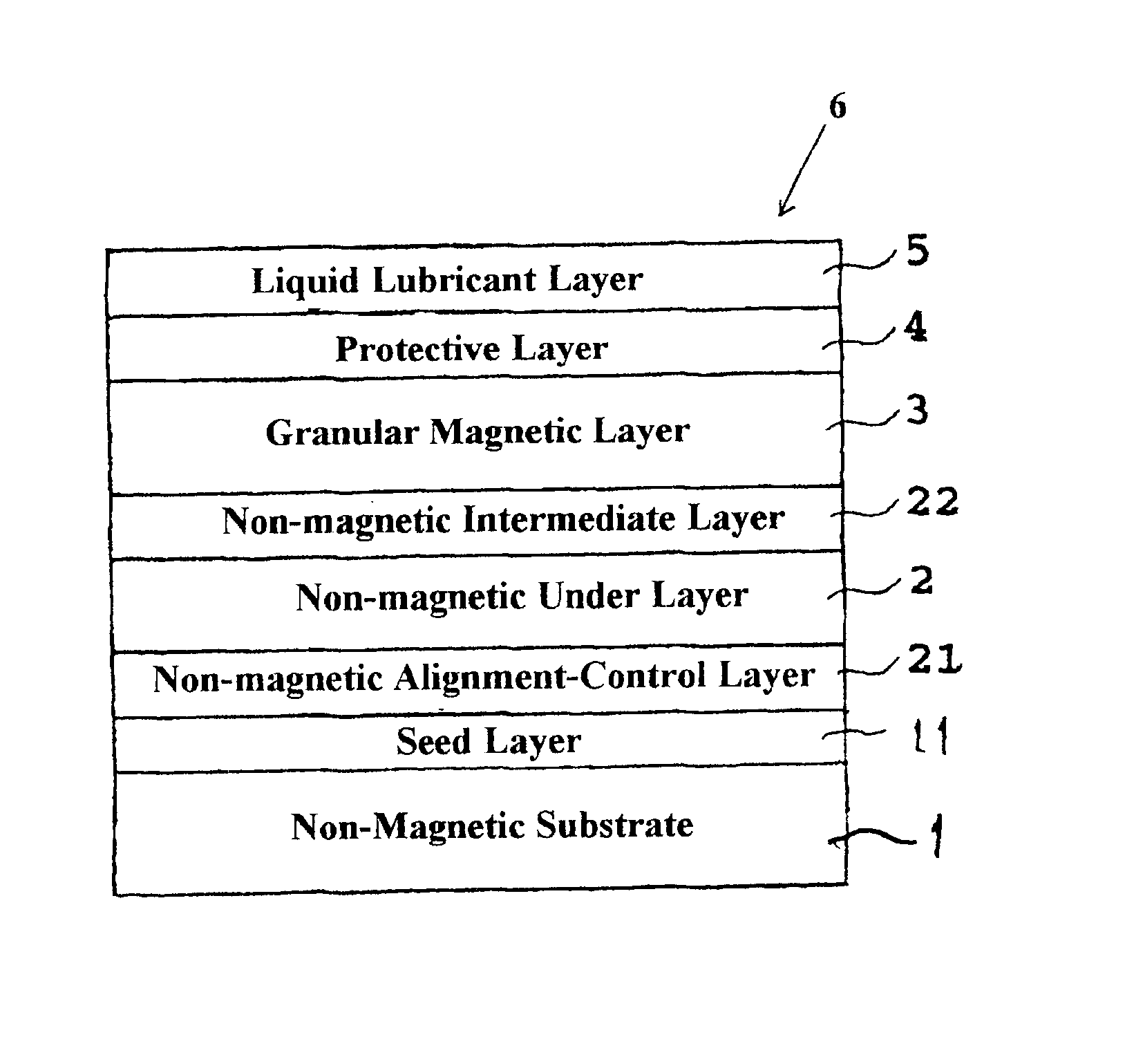
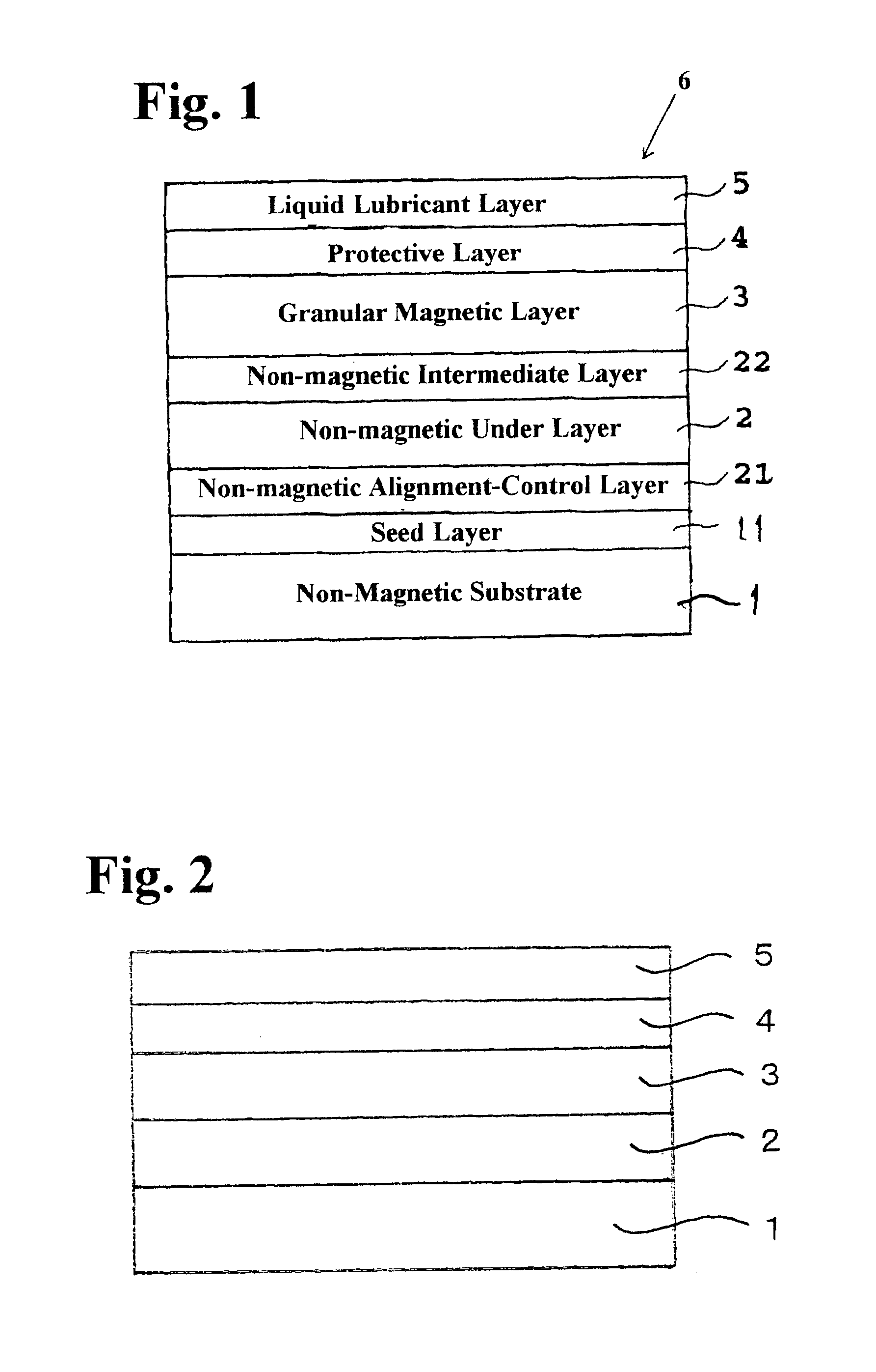
Referring now to FIG. 5, another embodiment of a magnetic recording medium was produced in the same manner as in Example 1 except that a non-magnetic intermediate layer 22 was formed on under-layer 3. Non-magnetic intermediate layer 22 was formed under an argon gas pressure of 5 mTorr after laminating under-layer 2 on substrate 1. Non-magnetic intermediate layer 22 was formed using an alloy of Co-35 at % Cr having thickness of about 5 nm. RF bias of 150 W was applied when under-layer 2 was formed.

As in Example 1, coercive force Hc was measured for the produced medium using a vibrating sample magnetometer (VSM). Signal-to-noise ratio (SNR) at the linear recording density of 270 KFCl was measured by a spinning stand tester using a GMR head.

The results are shown in Table 1 below. For comparison, Table 1 also shows, the characteristics of a medium without an intermediate layer 22 (as in Comparative Example 1) to which an RF bias of 150 W was applied.

As noted in Table 1, when intermediat...

example 3

Referring now to FIG. 6, three media embodiments (I, ii, and iii, shown later) of magnetic recording media were produced, as in Example 1, with the exception that non-magnetic alignment-control layer 21 was formed between non-magnetic substrate 1 and non-magnetic under layer 2.

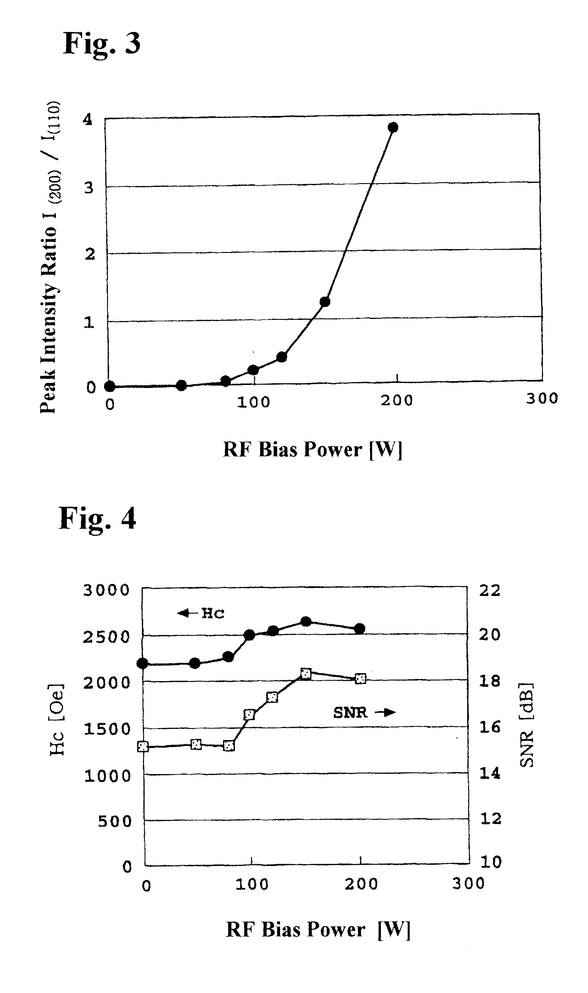
In this example, non-magnetic alignment-control layer 21, having a thickness of 30 nm, was formed by RF sputtering using various material under argon gas pressure of 8 mTorr before applying under-layer 2. RF bias was not applied during lamination of under-layer 2.

As in Examples 1 and 2, coercive force Hc was measured for each of the produced embodiments using a vibrating sample magnetometer (VSM). A signal-to-noise ratio (SNR), at the linear recording density of 270 KFCl, was measured by a spinning stand tester using a GMR head. The results are shown in Table 2.

Table 2 also shows intensity ratio I.sub.(200) / I.sub.(110) of the X-ray diffraction peaks of the under-layer of each medium. Table 2 further shows, fo...

example 4

Referring now to FIG. 7, an embodiment of a magnetic recording media was produced in the same manner as in Example 1 except that seed layer 11 and a non-magnetic alignment layer were applied between non-magnetic substrate 1 and non-magnetic under layer 2.

Seed layer 11 was formed by RF sputtering using various materials under the argon gas pressure of 5 mTorr and had a thickness of 30 nm. The subsequent non-magnetic alignment-control layer 21 of MgO, having thickness of 30 nm, was formed by RF sputtering prior to laminating under-layer 2. RF bias was not applied when under-layer 2 was laminated on non-magnetic alignment-control layer 21.

As in Examples 1, 2 and 3, coercive force Hc was measured for each of the produced media using a vibrating sample magnetometer (VSM). Signal-to-noise ratio (SNR) was measured for each produced media at the linear recording density of 270 kFCl. Signal-to-noise ratio (SNR) was measured by a spinning stand tester using a GMR head.

The results are shown in...


PUM

PropertyMeasurementUnit
thicknessaaaaaaaaaa
thicknessaaaaaaaaaa
thicknessaaaaaaaaaa

Abstract

A magnetic recording medium achieves excellent noise reduction by controlling the crystal orientation of a magnetic layer without thermal processing. The magnetic recording medium includes multiple layers laminated to a substrate. These layers include at least the magnetic layer and a non-magnetic under layer. The magnetic layer has a granular structure consisting of ferromagnetic grains with a hexagonal close-packed structure and non-magnetic grain boundaries composed mainly oxide or a nitride. The non-magnetic under-layer is a material having a body centered cubic crystal structure with a preferential orientation along a (200) plane parallel to a film surface of the under-layer.

Description

1. Field of the InventionThe present invention relates to a magnetic recording medium and a method for manufacturing the same. More particularly, the present invention relates to a magnetic recording medium used in magnetic recording devices, for example in computers.2. Description of the Related ArtHigh quality magnetic recording mediums require both high recording density and low noise. In an effort to achieve these goals, various compositions and structures for magnetic layers and non-magnetic under-layers have been proposed. Recently, a magnetic layer called a granular magnetic layer has been proposed having a structure, in which a ferromagnetic grain is surrounded by a non-magnetic and non-metallic substance, such as an oxide or a nitride.Technology related to the granular magnetic layer is shown in Japanese Unexamined Patent Application Publication No. H8-255342 and U.S. Pat. No. 5,679,473.In Japanese No. H8-255342, a method for manufacturing a magnetic recording medium compri...

Claims


Application Information

Patent Timeline
Patent Type & Authority Patents(United States)
IPC IPC(8): G11B5/73G11B5/62G11B5/66G11B5/65G11B5/738G11B5/84H01F10/16H01F41/16H01F41/18
CPCG11B5/66G11B5/732G11B5/7325Y10T428/265Y10S428/90G11B5/7379G11B5/73921G11B5/737G11B5/73923G11B5/7377
Inventor OIKAWA, TADAAKIUWAZUMI, HIROYUKISHIMIZU, TAKAHIROTAKIZAWA, NAOKI
Owner FUJI ELECTRIC CO LTD
Why Eureka
Try Eureka