

Method and apparatus for casting near-net shape articles
a technology of near-net shape and casting method, which is applied in the direction of wind motors with parallel air flow, wind motors with perpendicular air flow, foundry moulds, etc., can solve the problems of only operating at temperatures, and the processing of materials such as near-net shapes, which remains a significant technical challenge, so as to reduce the risk of localized premature solidification and enhance the performance of mold assembly
Inactive Publication Date: 2004-01-13
GENERAL ELECTRIC CO
View PDF3 Cites 75 Cited by
- Summary
- Abstract
- Description
- Claims
- Application Information
AI Technical Summary
Benefits of technology
Enables the production of near-net shape articles with improved mechanical properties and reduced porosity, overcoming the challenges of reactivity and temperature control in casting refractory metal intermetallic composites.
Problems solved by technology
However, turbine components such as, for example, airfoils in modern jet engines--can only operate at temperatures as up to about 1,150.degree. C., which is about 85% of the melting temperatures of most Ni-based superalloys.
Although the properties of this class of materials are attractive for use in advanced high-temperature applications, such as gas turbine assemblies, processing such materials, especially to near-net shapes, remains a significant technical challenge.
Method used
View moreImage
Smart ImageViewing Examples

Examples
example 2
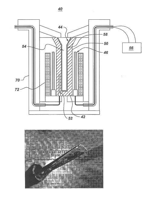
An airfoil having the composition of 50 atomic percent Nb, 23 atomic percent Ti, 2 atomic percent Hf, 16 atomic percent Si, 1.5 atomic percent Ge, 4 atomic percent Cr, 3 atomic percent Al, and 1 atomic percent Sn was cast using the apparatus of the present invention. The mold assembly used to cast the airfoil comprised an alumina mold, or shell, and a zircon facecoat. The mold was preheated to a temperature of about 1300.degree. C. The cast airfoil is shown in FIGS. 5a, 5b, and 5c. This result demonstrates that Nb--Si based composite materials can be investment cast into different near-net-shape articles, including airfoils, using the apparatus and methods of the present invention.
Login to View More PUM
| Property | Measurement | Unit |
|---|---|---|
| melting temperature | aaaaa | aaaaa |
| thickness | aaaaa | aaaaa |
| thickness | aaaaa | aaaaa |
Abstract
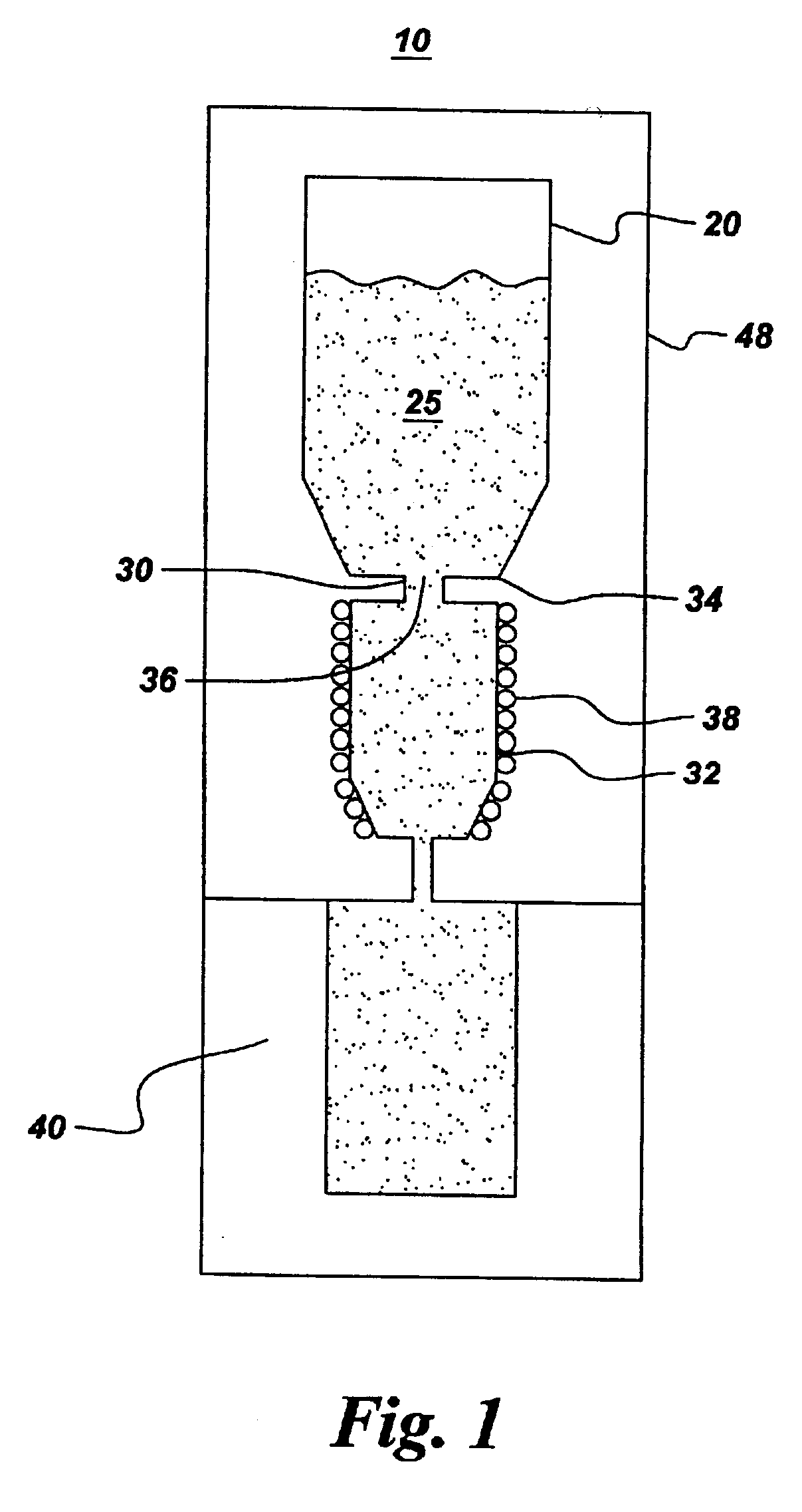
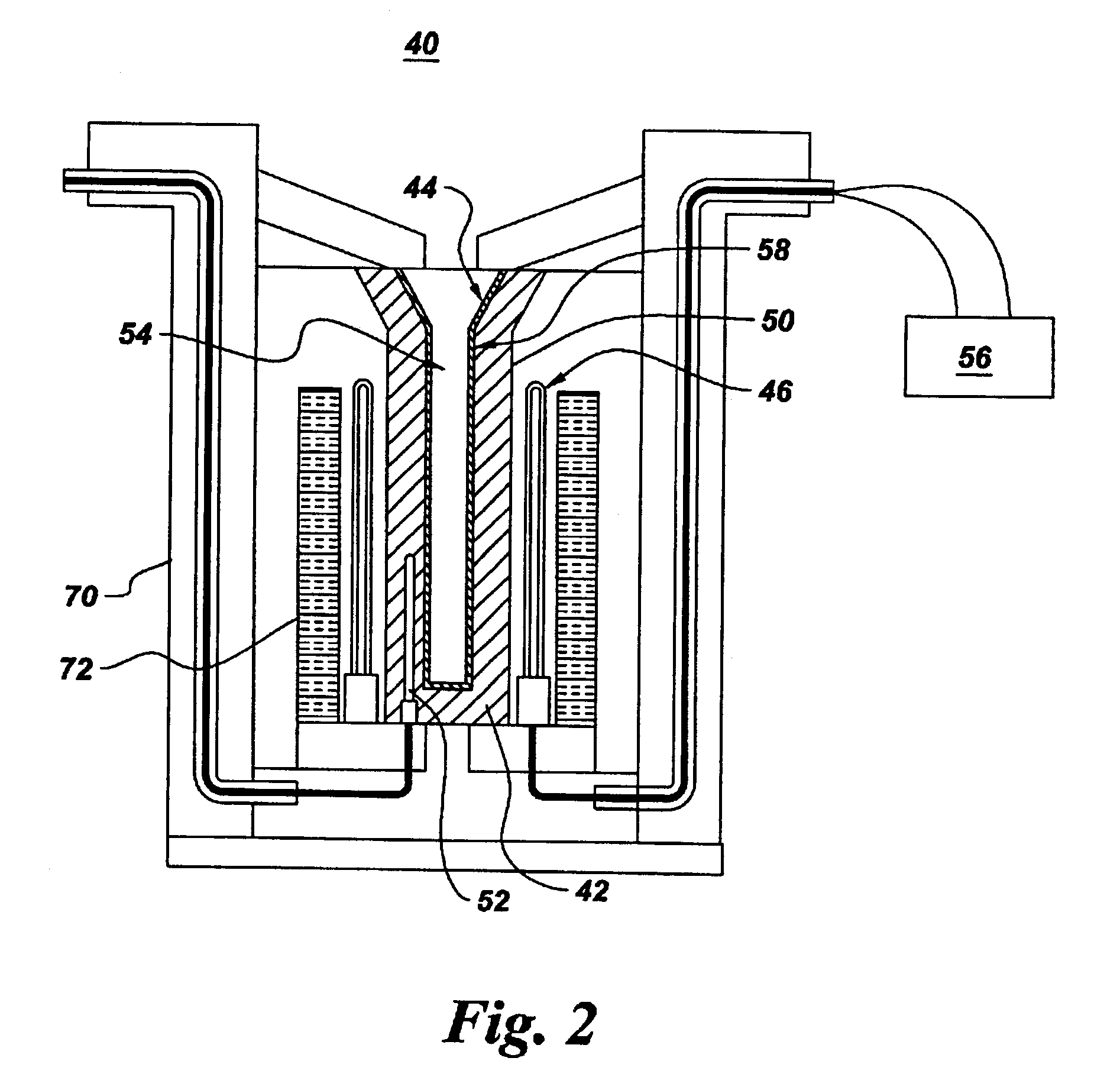
A method and apparatus for casting a near-net-shape article from a high temperature material, such as a refractory metal intermetallic composite material. The apparatus includes: a means for forming a molten material comprising at least one of a metal and an alloy; a means for pouring the molten material; a mold assembly comprising a solid shell having a face coat interposed between the solid shell and molten material; and a heater assembly for maintaining the solid shell at a temperature. The molten material solidifies within the solid shell to form a near-net shape of the article. The near-net shape article may be a turbine assembly component, such as, but not limited to, a vane or airfoil.
Description
BACKGROUND OF INVENTIONThe present invention relates to casting a near-net-shape article. More particularly, the present invention relates to an apparatus for casting a near-net shape article, such as, for example, an airfoil for a gas turbine assembly, from high-temperature materials, such as niobium-base suicides and molybdenum-base silicides. The present invention also relates to methods for casting a near-net-shape article.In a gas turbine assembly, such as an aeronautical turbine, a land-based turbine, a marine-based turbine, and the like, compressed air is mixed with fuel in a combustor and ignited, generating a flow of hot combustion gases through one or more turbine stages that extract energy from the gas, producing output power. Each turbine stage includes a stator nozzle having vanes that direct the combustion gases against a corresponding row of turbine blades extending radially outwardly from a supporting rotor disk. The vanes and blades include airfoils having a general...
Claims
Login to View More Application Information
Patent Timeline
 Patent Type & AuthorityPatents(United States)
IPC IPC(8): B22D27/04F01D5/28
CPCB22D27/04F01D5/28Y02T50/67Y02T50/672F05D2230/21F05D2300/13Y02T50/60
InventorSUBRAMANIAN, PAZHAYANNUR RAMANATHANJACKSON, MELVIN ROBERTDUPREE, PAUL LEONARDBEWLAY, BERNARD PATRICKEVENDEN, THEODORE MCCALL
OwnerGENERAL ELECTRIC CO