
Magnetic recording medium and its manufacturing method and magnetic recording system using such a magnetic recording medium

a manufacturing method and magnetic recording technology, applied in the field of perpendicular magnetic recording medium, can solve the problems of poor coercivity, thermal stability, poor magnetic anisotropy, coercivity and thermal stability of the magnetic layer with many stacking faults, and achieve the effect of economic advantage and good thermal stability

Inactive Publication Date: 2004-03-23
HITACHI GLOBAL STORAGE TECH JAPAN LTD
View PDF6 Cites 13 Cited by
  • Summary
  • Abstract
  • Description
  • Claims
  • Application Information

AI Technical Summary

Benefits of technology

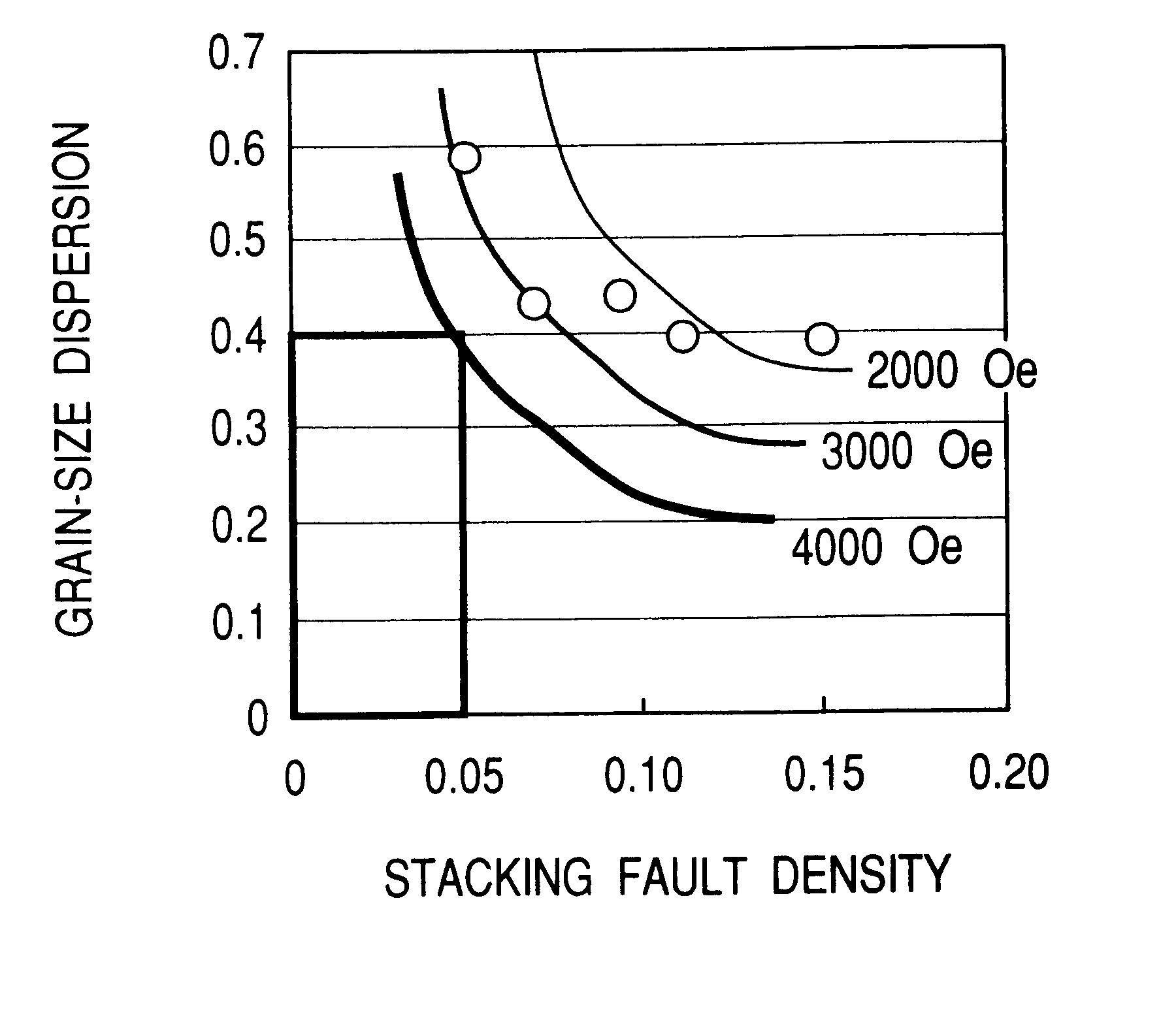
It is an object of the present invention to provide a perpendicular magnetic recording medium which is made of conventional CoCr alloy as a magnetic material and yet has good thermal stability owing to adequate control over the stacking fault density and the dispersion of particle diameters. Being made of a conventional magnetic material, the recording medium is economically advantageous.
It is another object of the present invention to provide a method of adequately controlling the stacking fault density and the dispersion of particle diameters.

Problems solved by technology

However, extremely small crystal grains encounter problems with thermal decay.
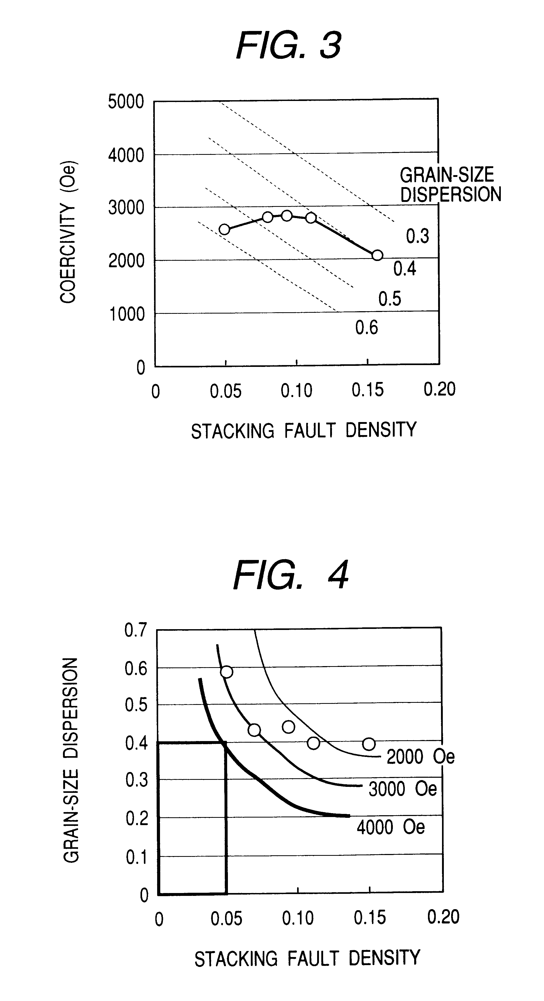
No matter whether it is of longitudinal recording type or perpendicular recording type, the magnetic layer with many stacking faults will be poor in magnetic anisotropy, coercivity, and thermal stability.
The major cause of stacking faults is ingression of a plane corresponding to the fcc-like structure into the hcp structure.
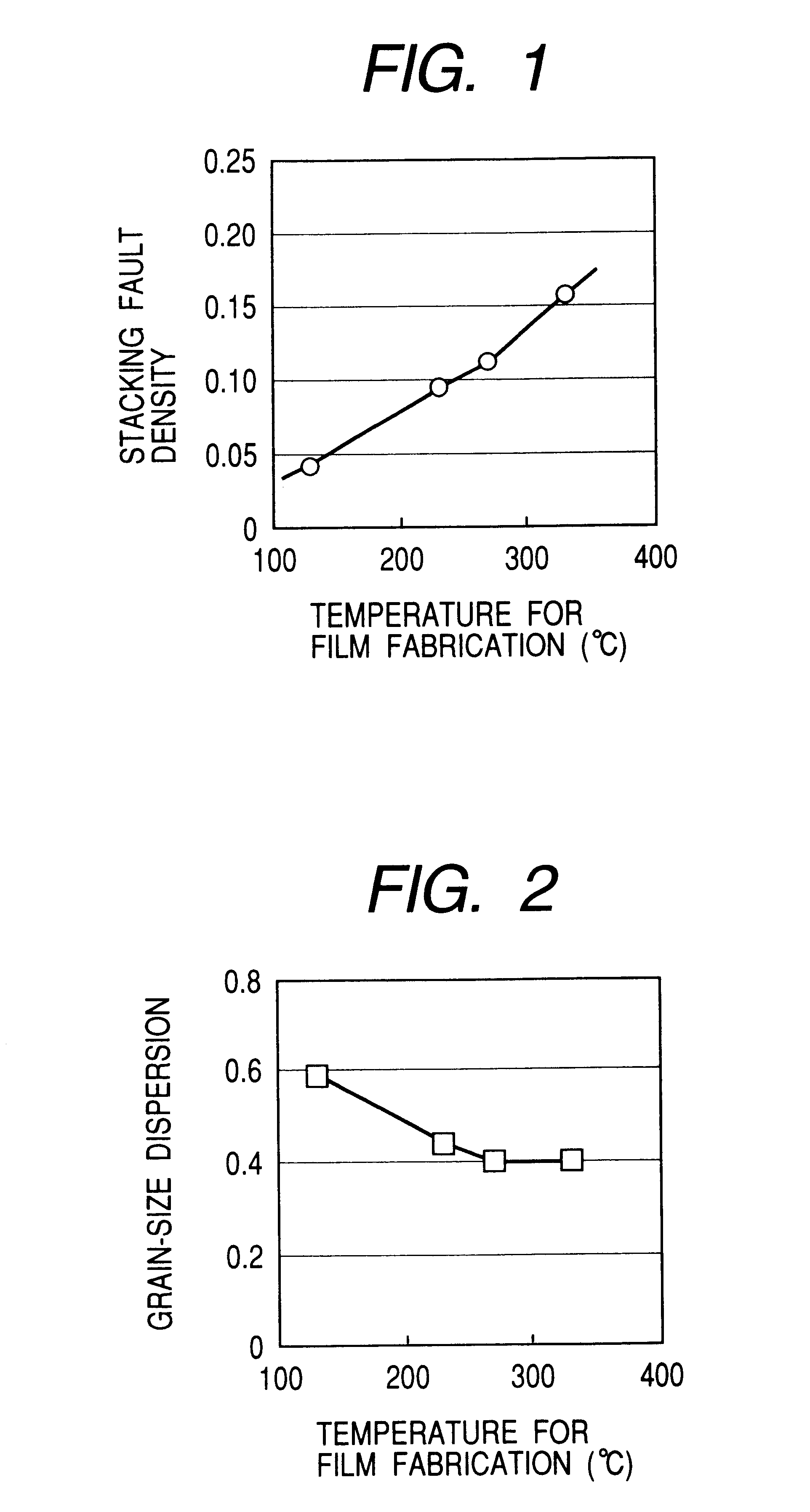
This suggests that it is difficult to have both of a low stacking fault density and a low dispersion of particle diameters.

Method used


Image

  • Magnetic recording medium and its manufacturing method and magnetic recording system using such a magnetic recording medium
  • Magnetic recording medium and its manufacturing method and magnetic recording system using such a magnetic recording medium
  • Magnetic recording medium and its manufacturing method and magnetic recording system using such a magnetic recording medium

Examples


example 2

The same procedure as in Example 1 was repeated except that annealing was carried out at a lower temperature and for a longer time. The resulting sample was tested for magnetic characteristics. There is an instance where annealing is performed on a number of magnetic recording media. In practice, however, it is usually impossible to hold all of them in a sputtering vacuum chamber with a limited capacity. So, it is necessary to remove them out of a vacuum chamber. This is the reason why the magnetic recording medium needs a protective film for protection from oxidation. The protective film should preferably be made of a carbonaceous material. To prevent carbon in the protective film from diffusing into the magnetic film, it is necessary not to heat the magnetic medium above 250.degree. C.

The sample of the magnetic recording medium in this example is somewhat similar in structure to that in Example 1. It is composed of the following layers.

Intermediate layer: a laminate composed of a ...

example 3

This example demonstrates the effect that is produced by controlling the dispersion of angles of c-axis. One effective way to reduce the dispersion of particle diameters is to increase the dispersion of angles of c-axis of the columnar crystal grains constituting the magnetic film. The dispersion of angles of c-axis is defined as the full width at half maximum of the dispersion of the angles which the (00.1) plane makes with the surface of the substrate. It is considered that the crystal grains constituting the magnetic film grow from the nuclei which have been randomly generated during sputtering. If those crystal grains which have grown from such nuclei become independent crystal grains, then the dispersion of particle diameters should be about 0.28 according to simulation with Voronoi figure. However, practical crystal growth takes place such that adjoining particles coalesce into a single particle. This is true particularly with crystal grains with a small dispersion of angles o...

example 4

This example demonstrates the effect which is produced by reducing the amount of platinum. The sample of the magnetic recording medium in this example has a soft magnetic film of FeTa(10)C(6), a 5-nm thick intermediate film of NiTa(37.5)Zr(10), a 6-nm thick film of CoCr(17)Pt(8) (as a first magnetic layer), a 12-nm thick film of CoCr(19)Pt(16) (as a second magnetic layer), and a protective carbon layer. The total thickness of the magnetic layer is 18 nm. The soft magnetic film of FeTa(10)C(6) was heated at 250.degree. C. by an infrared lamp after its formation.

The sample was tested for magnetostatic characteristics by using a vibrating sample magnetometer. It was found to have a coercive force of 4000 Oe and a squareness ratio of 1.0. After its test for magnetostatic characteristics, the magnetic layer was observed under a transmission electron microscope to examine the stacking fault density and the dispersion of particle diameters. It was found that the stacking fault density is 0...


PUM

PropertyMeasurementUnit
temperatureaaaaaaaaaa
coercive forceaaaaaaaaaa
particle diameteraaaaaaaaaa

Abstract

A magnetic recording medium having a high coercive force and being capable of high-density writing / reading has a substrate, a soft magnetic layer, a non-magnetic intermediate layer, a magnetic layer, a protective layer, and a lubricating layer. The magnetic layer is characterized by stacking fault density and dispersion of particle diameters. The stacking fault density should preferably be no larger than 0.05, and the dispersion of particle diameters should preferably be no larger than 0.4. The magnetic recording medium has a coercive force larger than 4000 Oe, is highly stable to thermal decay, and has a recording density in excess of 50 Gbit / in<2>.

Description

1. Field of the InventionThe present invention relates to a perpendicular magnetic recording medium, a process of production thereof, and a magnetic storage equipped therewith. The perpendicular magnetic recording medium has a magnetic layer composed of columnar magnetic crystal grains whose principal component is cobalt, and it is characterized by reduced thermal decay. The magnetic storage has a recording density in excess of 50 Gbit / in.sup.2.2. Description of the Related ArtsThere is an increasing demand for higher recording density in magnetic storage from the standpoint of increasing the storage capacity, miniaturizing the apparatus, and reducing the number of parts. The existing magnetic recording medium is based on longitudinal magnetic recording. It records information by means of mutually opposed domains (recording bits) which are magnetized in the direction parallel to the surface of the substrate. For a longitudinal magnetic recording medium to be capable of high-density ...

Claims


Application Information

Patent Timeline
Patent Type & Authority Patents(United States)
IPC IPC(8): G11B5/84G11B5/64G11B5/66G11B5/65G11B5/738G11B5/851H01F10/16
CPCG11B5/64G11B5/66G11B5/84Y10T428/31Y10T428/12875Y10T428/12465G11B5/672
Inventor TAKAHASHI, YOSHIOTANAHASHI, KIWAMUHOSOE, YUZURUTAMAI, ICHIRO
Owner HITACHI GLOBAL STORAGE TECH JAPAN LTD
Learn More