Spectral instrument using multiple non-interfering optical beam paths and elements for use therewith

a spectral instrument and optical beam technology, applied in the direction of instruments, spectrometry/spectrophotometry/monochromators, optical radiation measurement, etc., can solve the problems of insufficient stray light rejection, disadvantage or inconvenience, and many currently-available devices that do not have the resolution nor precision to accomplish many tasks, etc., to reduce scatter, increase dispersion, and reduce scatter

Inactive Publication Date: 2004-03-30
RYER DAMOND V
View PDF6 Cites 104 Cited by
  • Summary
  • Abstract
  • Description
  • Claims
  • Application Information

AI Technical Summary

Benefits of technology

Particularly, the present invention provides for a double pass through the grating to increase dispersion, reduce scatter while maintaining a perfect temperature-independent spectral match for the second pass. Using the grating twice reduces scatter by about a factor of 1000, increases the dispersion by a factor of two, and eliminates any temperature-related mechanical spectral drift which often is present with two separate monochromators.
One aspect of the invention is a specially designed grating which is moveable through a defined number of degrees--in the preferred embodiment the movement is through about 25 degrees of rotation about an optical axis of the grating component. In part because of the specially designed grating component, the grating can cause the concurrent diffraction of a plurality of incident optical beams, each of which beams have different angles of incidence and different angles of reflection. It is important to no

Problems solved by technology

Currently, a spectrometer that performs spectrometry, spectroradiometry, and spectrophotometry is a large, immobile device, not amenable to mobile applications.
In addition, many of these currently-available devices do not have the resolution nor the precision to accomplish the many tasks for which a spectrometer could be useful.
One common problem is inadequate stray light rejection.
Other issues with currently-available spectrometers, which issues are considered to be of disadvantage or inconvenience, include complex operating procedures, frequent recalibration requirements, and the oxidation of the optics.
Most spectroscopy systems which are reasonably priced and which are relatively easy to use do not provide for accurate and stable measurements.
There

Method used


Image

  • Spectral instrument using multiple non-interfering optical beam paths and elements for use therewith
  • Spectral instrument using multiple non-interfering optical beam paths and elements for use therewith
  • Spectral instrument using multiple non-interfering optical beam paths and elements for use therewith

Examples


Embodiment Construction

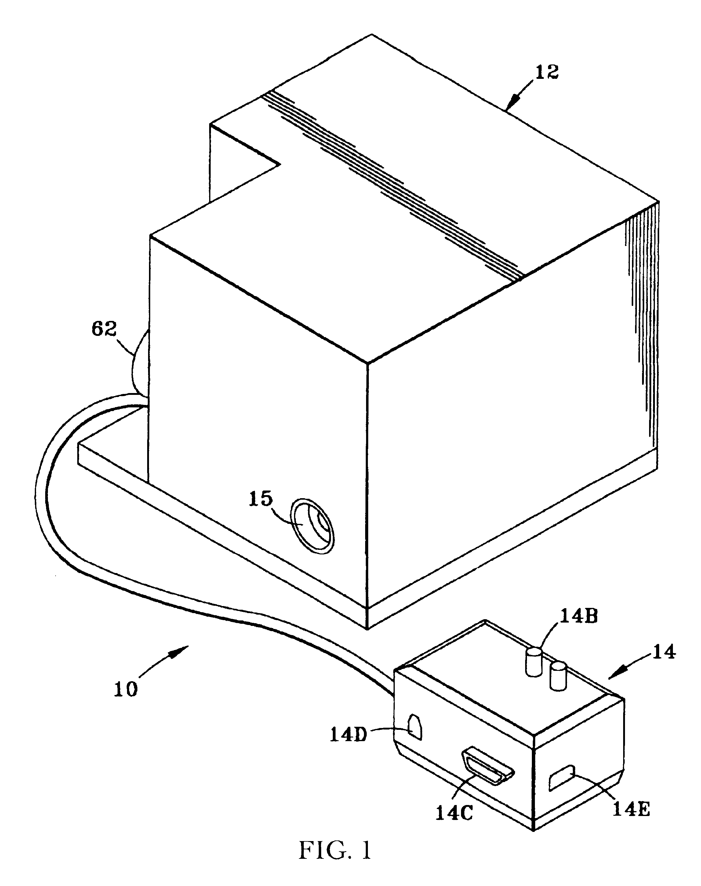
Referring to FIG. 1, system 10 comprises spectral instrument / spectrometer 12 attached by cable to power and interface model 14 which houses 12 volt dc input power connection 14B, RS232 serial communications port 14C, RJ11 telephone connector 14D, and 100-260 VAC input power connector. System 10 may also include software for use with a computer for the remote control of the spectral instrument 12. The control device, i.e., either a special purpose computer with most of the functions being hard-wired or incorporated into programmable chips (e-proms) or a general purpose computer capable of loading and processing the software, is not shown. The specifications of either control device is well known and by itself is not considered within the scope of the present spectrometer system.

The Spectral Instrument

Following is a disclosure of the many advantages, features, and uses of the spectral instrument of the invention. This information is provided to better describe the preferred embodiment...


PUM


Abstract

A spectrometer, or a spectral instrument using multiple non-interfering optical beam paths and special optical elements. The special optical elements for use with the instrument are used for directing the optical beam and/or altering the form of the beam. The instrument has the potential, depending upon the totality of the optical components incorporated into the instrument, to be a monochromator, a spectroradiometer, a spectrophotometer and a spectral source. The spectral instrument may further be a part of the spectral system. The system may include the spectral instrument, a power module and means for remote control of the instrument. Such remote control may be by use of a personal computer or a control system dedicated to the control, measurement and analysis of the collected information. The multiple non-interfering beam paths are created using specially designed optical elements such as a diffraction grating, a splitter box, a zero back-lash drive system for movement of the grating element. The orientation of and a physical/spatial relationship between the field lenses, slits, return mirror, reflecting prism, turning lenses all define the multiple, preferably two paths. Particularly, there is a double pass through the grating to increase dispersion, reduce scatter while maintaining a perfect temperature independent spectral match for the second pass. Using the same grating twice reduces scatter by about a factor of 1000, increases the dispersion by a factor of two, and eliminates any temperature-related mechanical spectral drift which often is present with two separate monochromators. Because of the specially designed grating structure, the grating can cause the concurrent diffraction of a plurality of incident optical beams, each of which beams have different angles of incidence and different angles of reflection. The path of the incident and the reflected beam to and from the grating is "off-axis". That is, the beams going to and from the grating do not use the optical axis of the grating structure.

Description

Not Applicable.1. Field of the InventionThe instant invention most generally relates to spectrometers and spectral instruments. Particularly this invention relates to the manipulating and the directing of electromagnetic beams, preferably within the optical spectrum. More particularly, using appropriate optical elements, a plurality of non-interfering beams paths are created and each of which beams are controlled, directed as to the paths, and shaped, dispersed, diffracted and otherwise manipulated. The manipulation, directing, redirecting, diffracting, frequency selection and the like, accomplished to each of the beams of the plurality of beams is accomplished by some of the same elements. More particularly, there are two beams, a first or an in beam and a second or an out beam going in substantially opposing directions and passing through the same control, manipulation and direction elements concurrently and without interference. One beam manipulating element is a means for diffra...

Claims


Application Information

Patent Timeline
IPC IPC(8): G01J3/28G01J3/00G01J3/18G01J3/06G01J3/12G01J3/02
CPCG01J3/02G01J3/0208G01J3/0291G01J3/06G01J3/12G01J3/18G01J3/28G01J2003/1828
Inventor RYER, DAMOND V.
Owner RYER DAMOND V
Why Eureka
Try Eureka