
Method of laser casting copper-based composites

a technology of laser casting and composites, applied in the direction of additive manufacturing, process efficiency improvement, additive manufacturing apparatus, etc., can solve the problems of reducing the effect of coating the powder surface to improve heat absorption or reduce reflection, and affecting the effect of thermal insulation

Inactive Publication Date: 2004-04-20
SINGAPORE INST OF MFG TECH THE +1
View PDF15 Cites 31 Cited by
  • Summary
  • Abstract
  • Description
  • Claims
  • Application Information

AI Technical Summary

Benefits of technology

The invention is a method of laser casting copper-based materials using pure copper powder and other elements like nickel, iron, or tungsten. The method involves using a selective laser sintering process to directly melt the copper powder with the help of other elements like nickel or iron. This allows for the fabrication of complex three-dimensional objects using a process of layer-by-layer deposition. The method can also be used to produce composite materials by mixing copper powder with other powders like titanium carbide or titanium dioxide. The resulting parts have high density and require minimal post-processing. The method can be used with other laser sintering systems like EOSINT M or EOSINT M2. The invention also includes a method for directly laser sintering metallic powders to produce high-density parts with minimal distortion and porosity.

Problems solved by technology

Shrinkage of the built part after the debinder and infiltration process results in distortion.
The powder deposition mainly depended on the powder properties--in this case on the individual Cu or Fe powder properties--and resulted in compromises on the powder mixtures as well as in modifications of the deposition mechanism.
Attempts to coat the powder surface to improve heat absorption or reduce reflection are not always effective because of poor thermal coupling between the coating and the powder.
The reflectivity problem has been a barrier to the application of CO.sub.2 lasers to the melting of metals such as copper or gold.
However, Cu is not easily melted by CO.sub.2 laser due to its high reflectivity to the laser.

Method used


Image

  • Method of laser casting copper-based composites
  • Method of laser casting copper-based composites
  • Method of laser casting copper-based composites

Examples


example 1

Cu--Ni system

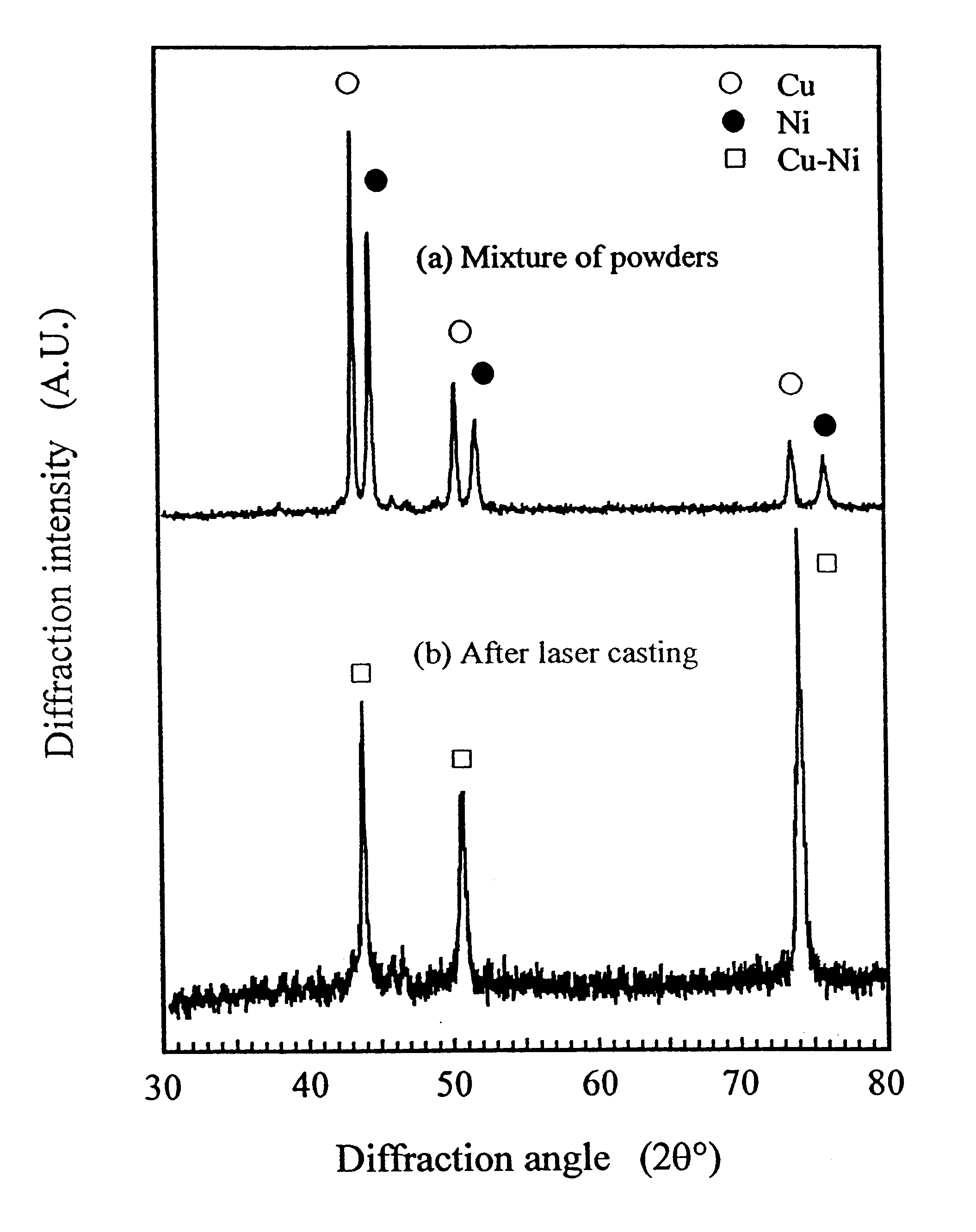
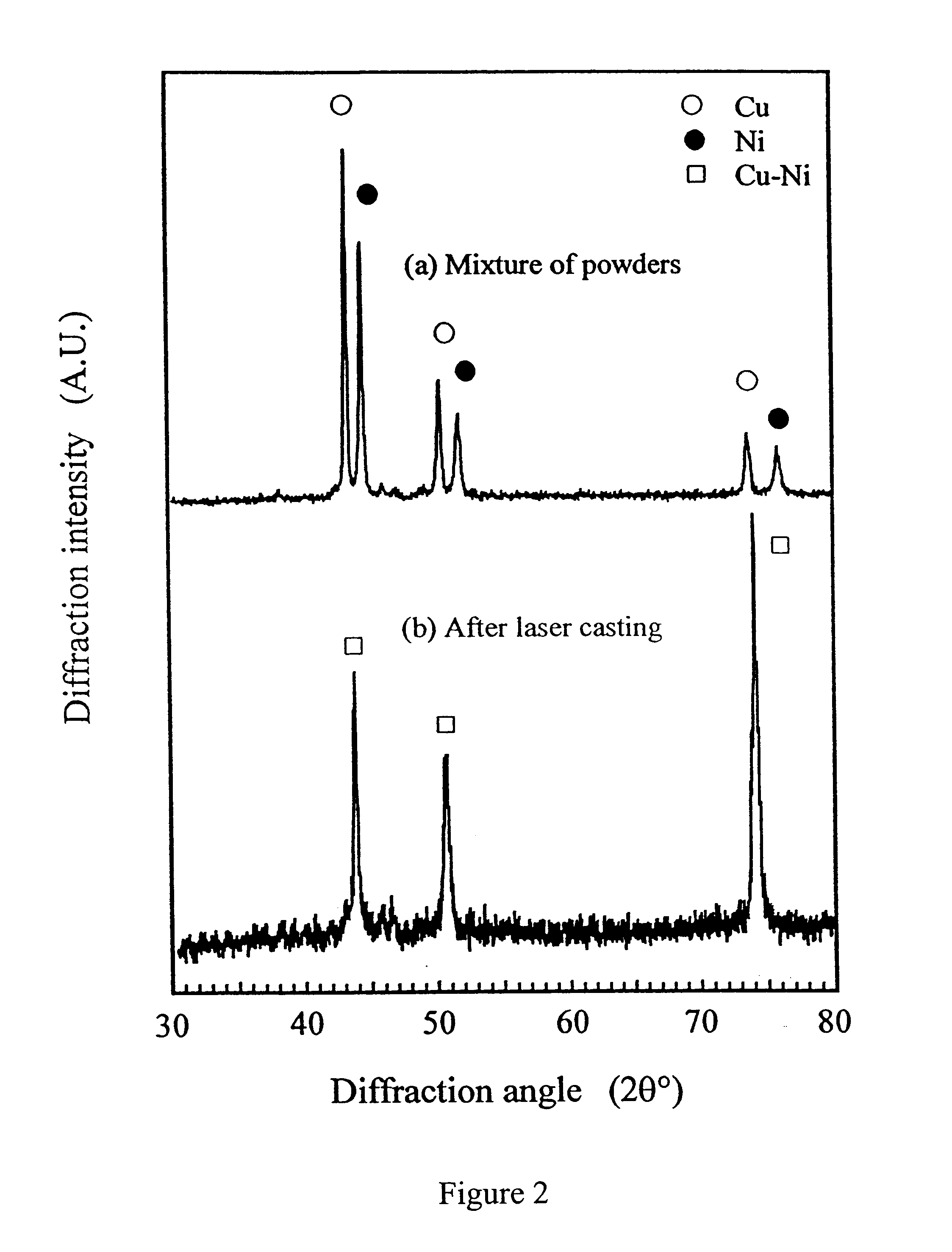
For the Cu and Ni powder system, the percentage of Ni was varied from 10% to 67% by weight. The powder mixture was first ball milled to form a powder mixture. After ball milling, laser casting was carried out. Formation of Cu--Ni solid solution was observed. Even at low percentages of Ni, the powder mixture could still be melted and formed into a dense part. The Cu--Ni powder system was therefore used as the matrix for Cu alloy based composites. FIGS. 2a and 2b show the X-ray diffraction (XRD) analysis results of the Cu--Ni powder system before and after the laser casting process. FIG. 2a shows the as-received Cu--Ni XRD spectrum where Cu and Ni diffraction peaks can be seen. After laser casting, pure Cu and Ni peaks disappeared and a new solid solution of Cu--Ni phase was detected. Microstructure of the laser cast Cu--Ni material is shown in FIG. 3a. Even at low percentage of Ni, a homogeneous phase has been formed without porosity. As can be seen in FIG. 3b, the laser...

example 2

Cu--WC (Ni) system

Cu was first ball milled with WC (with small amount of W.sub.2 C in the WC powder). Between 10% to 60% by weight of WC was used in the process. Structural analyses using X-ray diffraction before and after laser casting are shown in FIGS. 4a and 4b. X-ray diffraction spectra show no structural change after laser casting. Microstructure studies indicate porosity in the laser cast part when the powder mixture contains less than about 10% by weight of WC. FIG. 5a shows the microstructure of the laser cast Cu-6.7% WC composite. Porosity in the cast part can be seen in the figure. With increasing percentage of WC, porosity can be reduced. With the addition of Ni into the powder system (Cu--Ni matrix), the porosity was eliminated and a highly dense part of WC particles embedded in a solid solution of nickel in copper was formed. Ni addition can increase bonding between Cu and WC. The microphotograph in FIG. 5b shows that WC particles segregate at the boundaries of the cas...

example 3

Cu--Ti--C (Ni) system

Laser casting of Cu--Ti--C (Ni) should be well protected to avoid oxidation of Ti powder since it is very reactive. Besides the use of an Argon chamber, direct purging with Argon gas is also possible. In-situ formation of TiC was observed in Cu--Ti--C systems as shown in FIG. 6. The formation of in-situ TiC can be observed from the TiC diffraction peaks, as shown in FIG. 6b. After the laser scan, Ti and C reacted completely with each other and no Ti was detected from the XRD results. Microstructure analysis showed that TiC was well distributed in the matrix. However, the part formed after laser casting was found to be relatively porous. At high percentages of Ti and C (calculated resultant 50% TiC) in the powder mixture of Cu--Ti--C, the powder did not fuse together after the laser sintering process. With the addition of Ni (at about 10%), the powder fused together to form a part with low porosity. FIG. 7 shows the dense microstructure of the Cu--Ti--C--Ni syste...


PUM

PropertyMeasurementUnit
diameteraaaaaaaaaa
weight ratioaaaaaaaaaa
wavelengthaaaaaaaaaa

Abstract

This invention presents the process of direct laser casting of copper alloys: Cu-X (where X=Ni, Fe, W;) and their composites Cu-Y and Cu-X-Y (Y=WC, TiC, Ti+C) from powders prepared using mechanical mixing and ball milling processes. Since the metallic powder is combined with a low melting point Cu metal, which has good thermal and electrical conductivity, the combination allows the powder mixture to be melted by CO2 laser and re-solidified into a part with good mechanical properties and conductivity. The laser casting process for the Cu-based in-situ formation and the material systems formed using the said method have been developed. The process can be used to fabricate complex three-dimensional objects by multi-layer overlapping and the material systems can be used to build rapid tooling due to the properties of good thermal conductivity and low wear rate.

Description

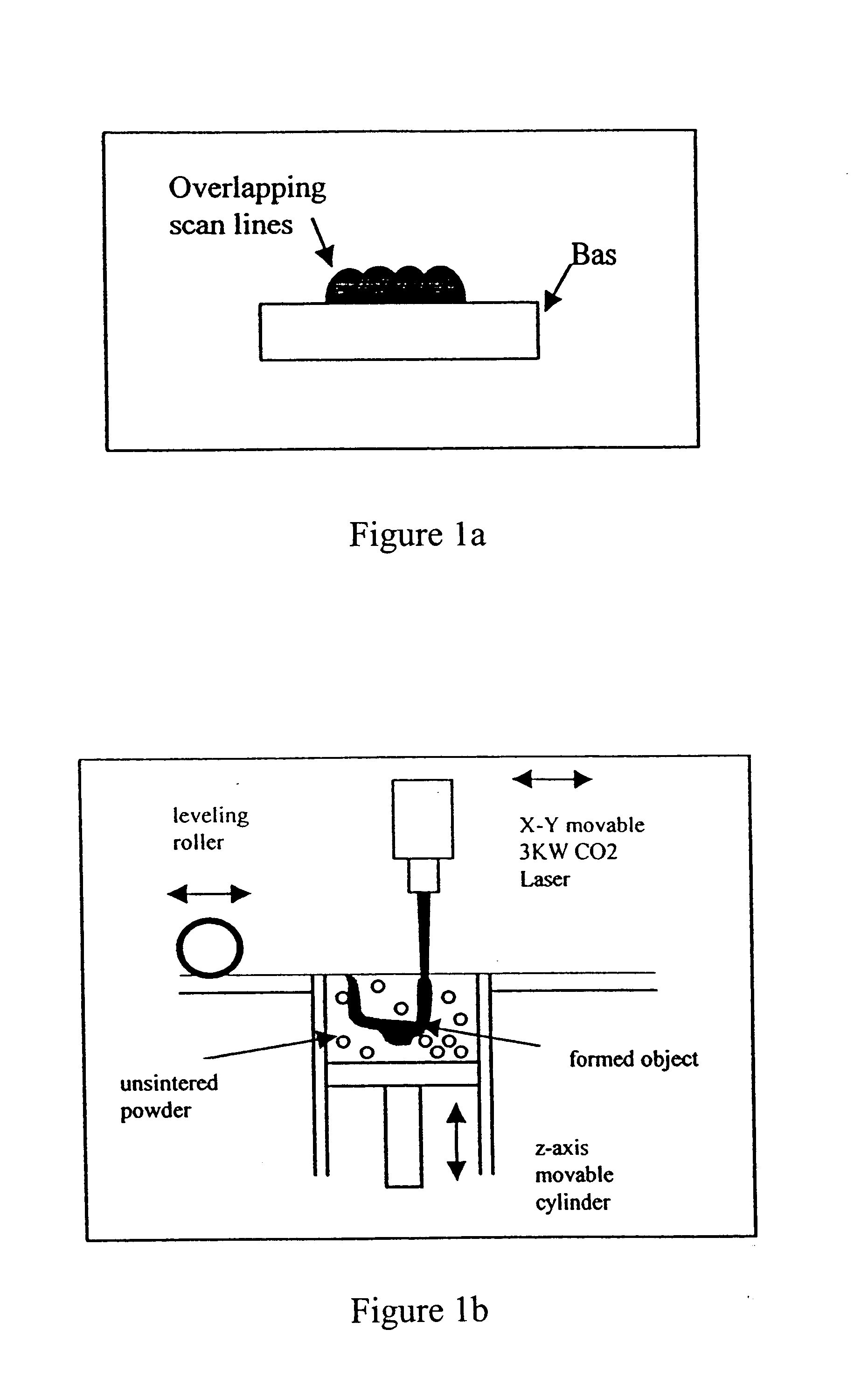
This invention relates to a method of laser casting, for example, a copper-based material. In particular, the invention presents a method to directly melt pure copper (Cu) powder with the help of other elements (X) such as, for example, (nickel (Ni), iron (Fe) or tungsten (W)) using CO.sub.2 laser. Using this technique, Cu alloys (Cu+X) and composites Cu-Y and Cu-X-Y (Y=tungsten carbide (WC), titanium carbide (TiC), titanium (Ti) and graphite (C)) can be synthesised from elemental powder mixtures which are prepared by mechanical mixing or milling processes. The developed laser casting process may advantageously be used to fabricate complex three-dimensional objects, by multi-layer overlapping, which may be used in electrical discharging machining (EDM) electrodes, rapid die and mould tooling, or other system components.BACKGROUND ART OF THE INVENTIONThe method and apparatus of selective laser sintering (SLS) are described in U.S. patents such as U.S. Pat. No. 4,863,538 (1989), U.S. ...

Claims


Application Information

Patent Timeline
Patent Type & Authority Patents(United States)
IPC IPC(8): B22F3/105
CPCB22F3/1055B22F1/0003B22F9/04B22F2003/1052B22F2009/041B22F2998/10B33Y10/00Y02P10/25B22F12/42B22F10/28B22F10/36B22F10/32B33Y40/10B22F1/00B22F1/09B22F1/12B22F10/20
Inventor LU, LIFUH, JERRY YINGWONG, YOKE SANCHEN, ZHENDALIM, GNIAN CHER
Owner SINGAPORE INST OF MFG TECH THE
Learn More