Vertical aligned liquid crystal display and method using dry deposited alignment layer films

Inactive Publication Date: 2004-04-20
INFOVISION OPTOELECTRONICS HLDG LTD +1
View PDF10 Cites 37 Cited by
  • Summary
  • Abstract
  • Description
  • Claims
  • Application Information

AI Technical Summary

Problems solved by technology

This results in light leakage near the ridge.
However, the first method is complicated and costly.
Also, the charge retention is usually poor, on the order of less then 80%, due to the use of the long chain alcohol material.
Furthermore, experimental results show th

Method used


Image

  • Vertical aligned liquid crystal display and method using dry deposited alignment layer films
  • Vertical aligned liquid crystal display and method using dry deposited alignment layer films
  • Vertical aligned liquid crystal display and method using dry deposited alignment layer films

Examples


first preferred embodiment

Truly Vertical Alignment

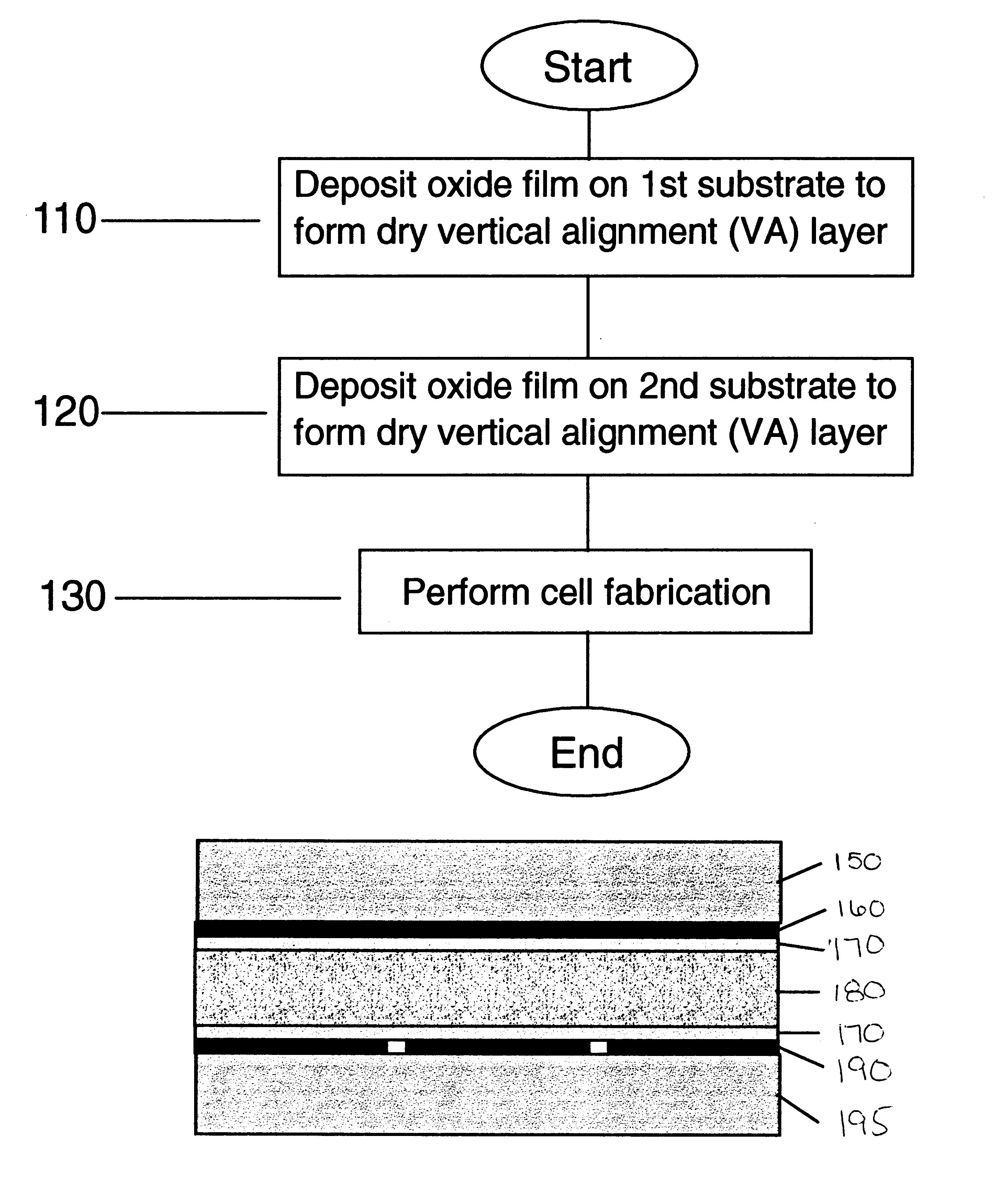
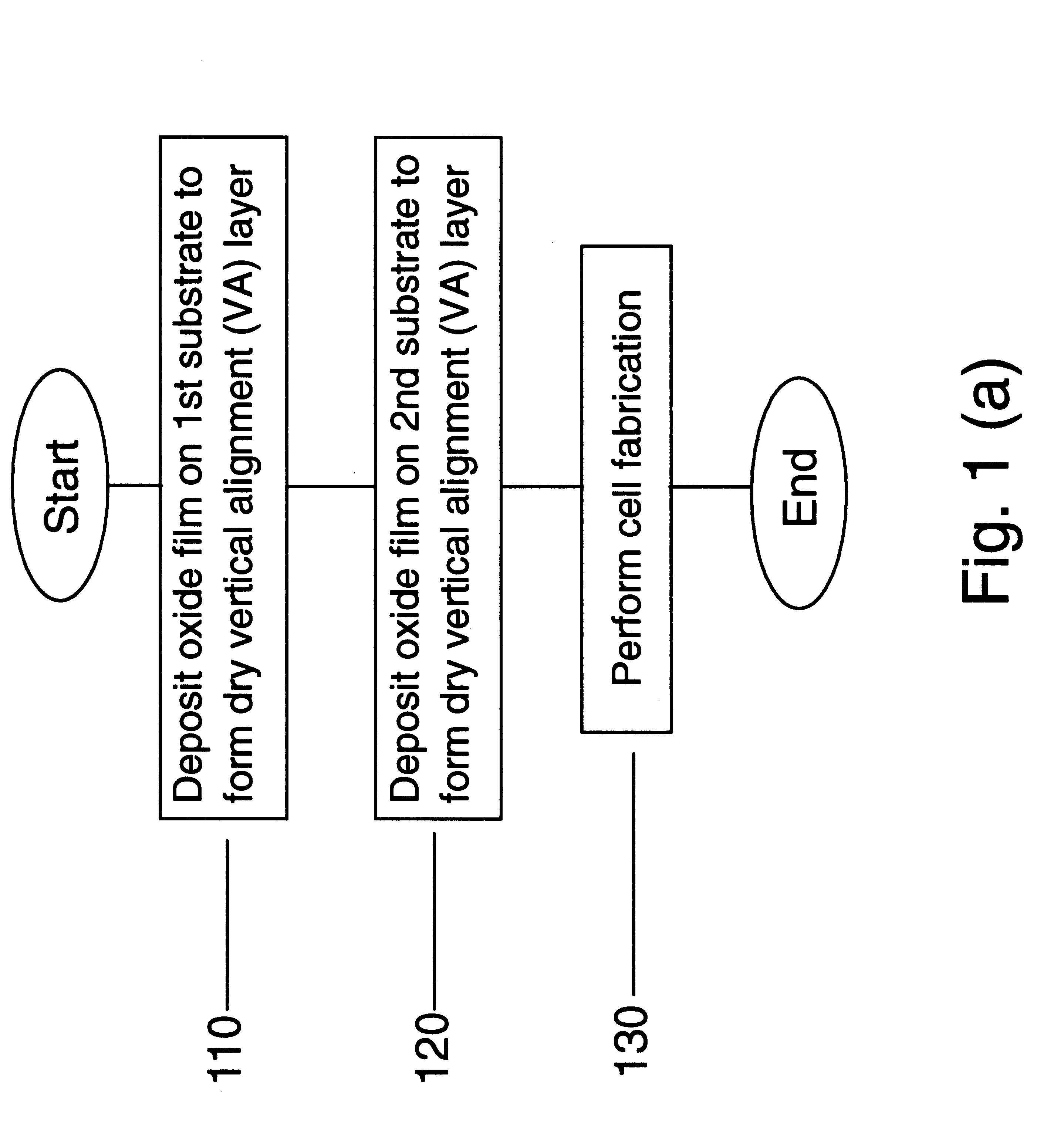
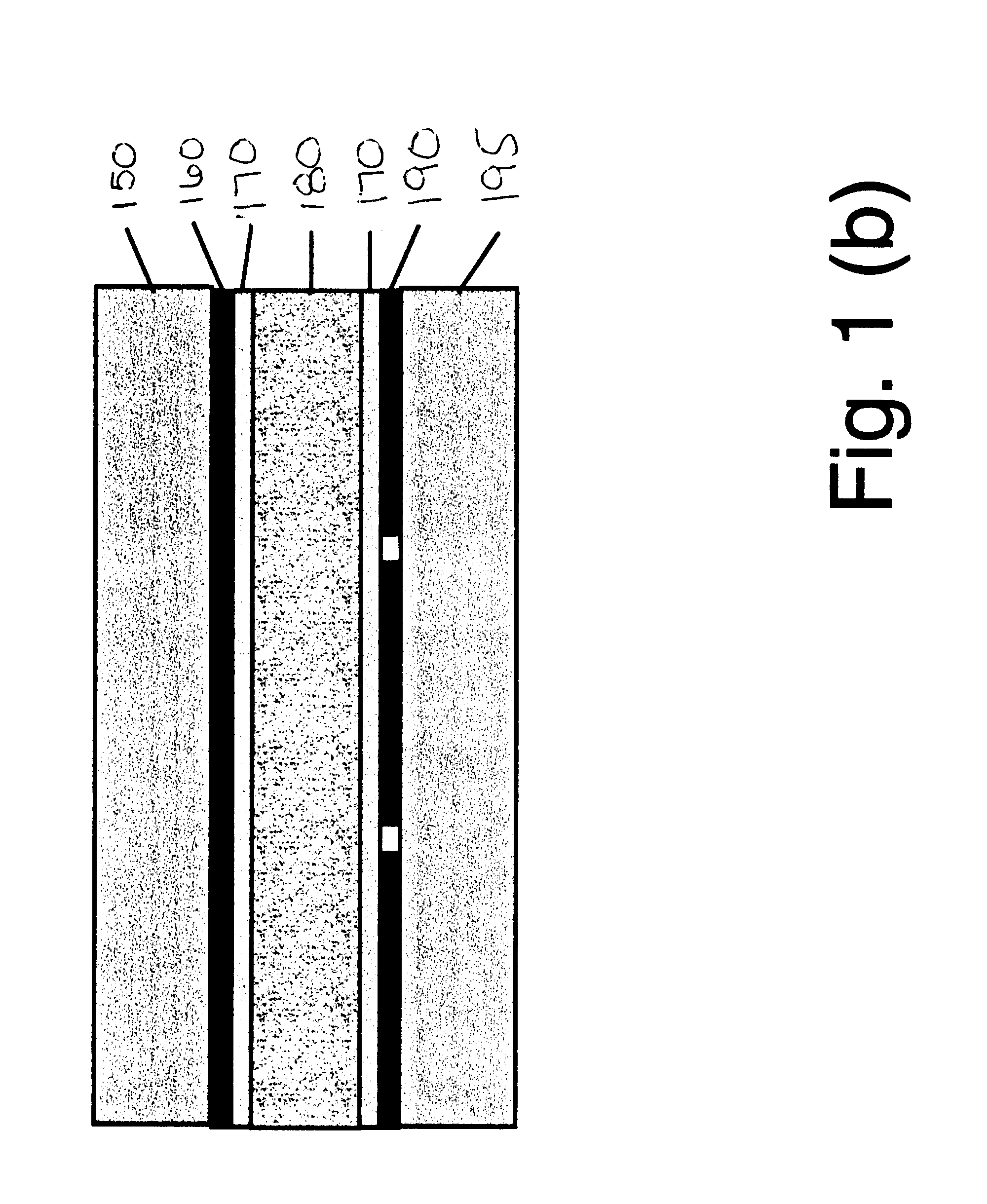
Turning to FIG. 1A, regarding a method 100 for producing a structure having truly vertical alignment (e.g., almost 90.degree.), in step 110, a substrate 150 (e.g., a glass substrate, quartz substrate, silicon-based substrate, plastic substrate, transparent substrate, reflective substrate, TFT substrate, any of these substrates with driving circuitry on it or any other suitable substrate) is deposited with a dry deposited vertical alignment film by one of the following deposition methods.

That is, a first deposition method includes a normal direction e-beam evaporation of silicon oxide film, in which the evaporant is SiO.sub.2, and the electron gun ("E gun") voltage is 7 kev. The preferred angle of the evaporant source to the substrate surface is 90.degree..+-.5.degree., and the deposition rate is 3 .ANG. / s. Preferably, the deposition pressure is approximately 1.5 e-6 torr. During deposition, the substrate temperature is at room temperature. The film thickness ...

second preferred embodiment

FIGS. 3A-3B show the structure of the conventional rectangular LCD cell of a TFT-LCD panel. FIG. 3A is a top view and FIG. 3B is a side view along A-A' cross-section. For simplicity, only the pixel electrode 301, and the gate and data bus lines, respectively, are shown. The TFT devices, the top plate electrode and color filter are not shown.

The top plate electrode (not shown) preferably is a continuous Indium tin oxide (I TO) electrode. In FIG. 3A, the polyimide (homogeneous or homeotropic) alignment layers (not shown) are used as liquid crystal alignment layers. This design is a single domain design which has a narrow viewing angle.

FIGS. 4A-4B illustrate a LCD cell design according to the second embodiment of the present invention. The structure of FIGS. 4A-4B is the same as that of FIGS. 3A-3B except that there is a polymer wall 401 (ridge) located on the top plate electrode in the middle of each pixel, and the dry vertical alignment film (not shown in FIG. 4a) which covers both t...


PUM


Abstract

A liquid crystal display device includes a first substrate, a dry alignment film deposited over the substrate, a second substrate coupled to the first substrate with the dry alignment film deposited over the second substrate therebetween and forming a cell gap, and a liquid crystal material formed in the cell gap. The dry alignment film allows for a truly vertical alignment of molecules of the liquid crystal material such that the molecules form an angle of substantially 90° relative to the substrate. The dry alignment film can be an oxide layer, a nitride layer, an oxynitride layer or a silicon layer. This dry alignment layer can be treated to form a tilted homeotropic alignment, such that the liquid crystal molecules have a pretilt angle of 0.5 to 10 degrees from a substrate normal direction. The truly vertical alignment process can be incorporated with a ridge and fringe field process method to form a multidomain Vertical Alignment (VA) Liquid Crystal Display's (LCDs) which have wide viewing angles.

Description

1. Field of the InventionThe present invention relates to a method of forming a liquid crystal cell for use in a liquid crystal display (LCD) and more particularly to a method of forming a vertically aligned liquid crystal cell using a dry alignment layer.2. Description of the Related ArtIt is well known that the vertical-crystal-aligned (VA) liquid crystal display (LCD) has a good black state, and thus it has a high contrast ratio. VA-LCD has been used in both the direct view thin film transistor-liquid crystal display (TFT-LCD) panel and the liquid crystal projection light valve.Two types of vertical alignment (VA) are commonly used. One is a "truly vertical alignment" (e.g., liquid crystal molecules are aligned 90.degree. to the substrate surface with zero pretilt). The other is a tilted homeotropic alignment (e.g., liquid crystal molecules are aligned to the substrate surface almost vertically with a small pretilt angle of, for example, 1.degree. to 10.degree., from the substrat...

Claims


Application Information

Patent Timeline
IPC IPC(8): G02F1/1337G02F1/13G02F1/1333
CPCG02F1/133734G02F1/133707G02F2001/133742G02F1/133742
Inventor ANDRY, PAUL STEPHENCAI, CHENCHAN, KEVIN KOKCHAUDHARI, PRAVEENDOYLE, JAMES PATRICKGALLIGAN, EILEEN ANNJOHN, RICHARD ALLENLACEY, JAMES ANDREWLIEN, SHUI-CHIH ALAN
Owner INFOVISION OPTOELECTRONICS HLDG LTD
Why Eureka
Try Eureka