
Surface plasmon resonance detection with high angular resolution and fast response time

a surface plasmon and detection technology, applied in the field of surface plasmon resonance detection with high angular resolution and fast response time, can solve the problems of increasing the sensitivity of the resonance angle measurement relationship between the intensity and the sensitivity of the resonance angle measurement, and the bulky setup is more susceptible to mechanical noise and thermal dri

Inactive Publication Date: 2004-08-31
FLORIDA INTERNATIONAL UNIVERSITY
View PDF6 Cites 20 Cited by
  • Summary
  • Abstract
  • Description
  • Claims
  • Application Information

AI Technical Summary

Problems solved by technology

For higher angular resolutions, a large distance between the prism and the photodetector is required which makes the setup not only bulky but also more susceptible to mechanical noise and thermal drift.
The response time is slow because of the mechanical movements in the setup.
A drawback, however, is that the relationship between the intensity and the sensitivity of the resonance angle measurement is dependent on the angle at which the photodetector is fixed.
Major limitations in the resolution of the method come from fluctuation in the intensity of the laser and from thermal and mechanical drift in the setup.
As mentioned above, these methods suffer two major drawbacks: slow response time and limited angular resolution.
The later one limits the sensitivity of SPR for detecting small amounts of molecules or small structural or conformational changes in molecules.
In the first method, the response is slow because of mechanical movements involved in the method.
For high angular resolution, both methods require a large distance between the sample and the detector, which makes the setups more susceptible to mechanical noise and thermal drift.
Large distances, however, deteriorate the quality of the detected beam and makes to the SPR instruments bulky.
For a given sample-detector distance, the resolution of the first method is limited by the precision of measuring the angular position of the prism.
The resolution of the second method is limited by the number of channels (pixels) in the photo detector array and the noise level in the measured intensity in each channel.
The second method suffers an additional problem, in that the intensity of the beam is spread out over many channels, which decreases the signal to noise ratio, and therefore limits the resolution.
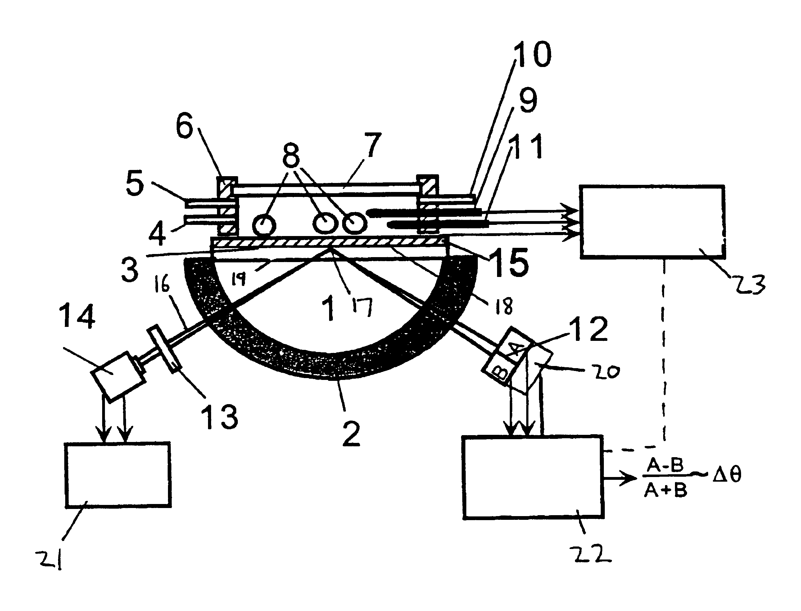
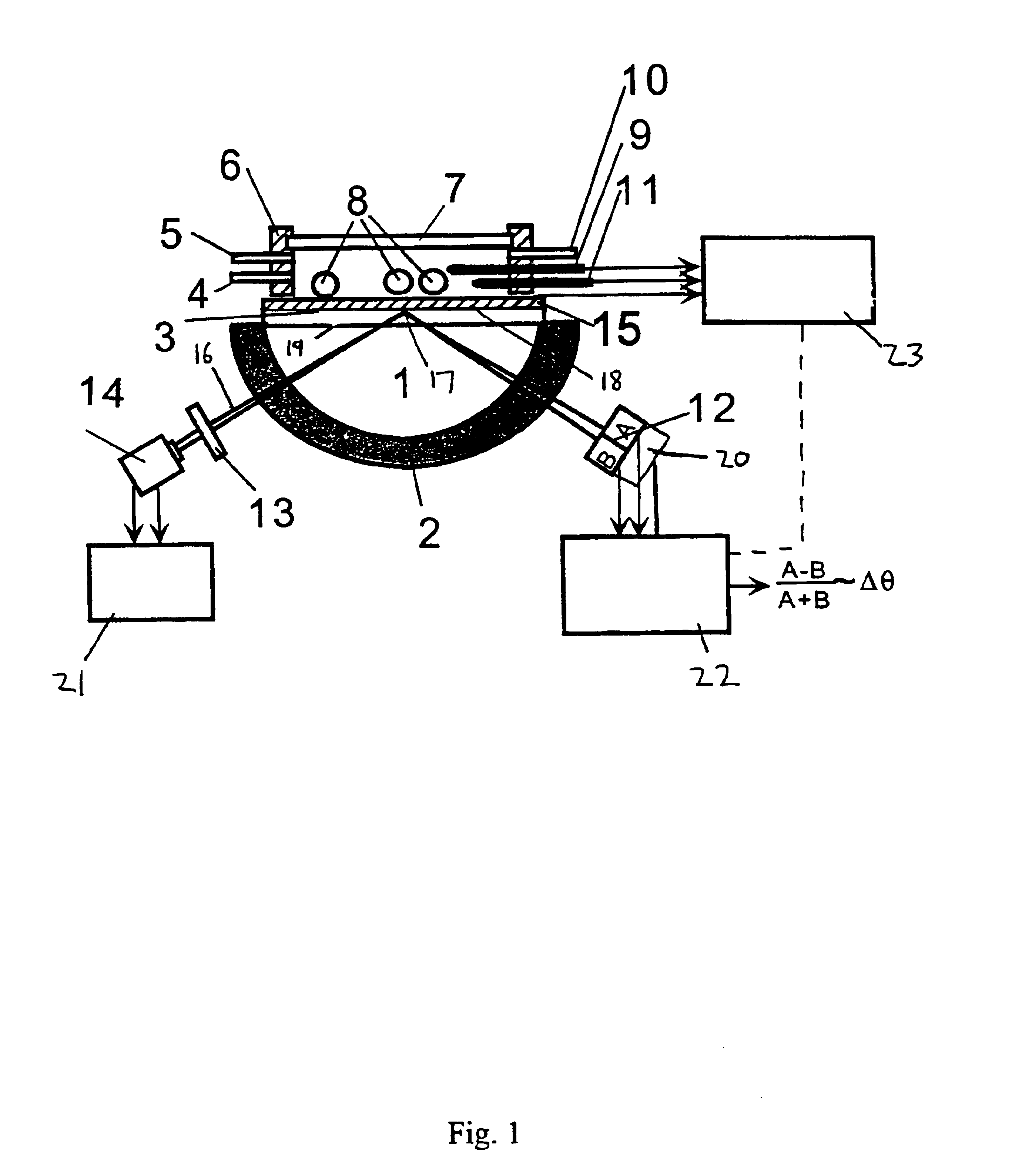
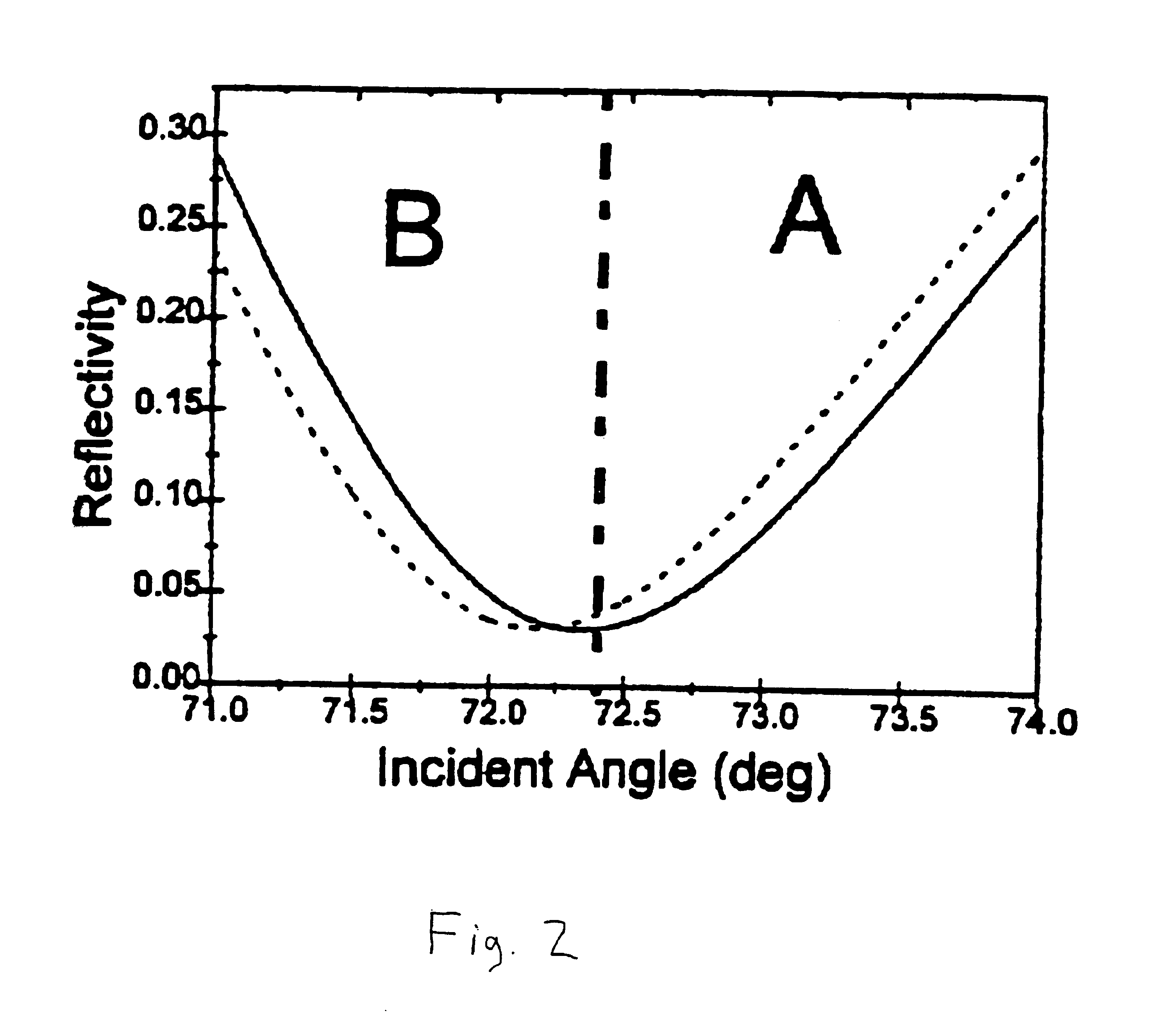
A shift in the SPR results in an intensity imbalance of the two cells (dashed lines) which is detected as the differential signal by the photodetector.
In contrast, high resolution in prior art sensors requires a large distance between the photodetector and the sample.

Method used


Image

  • Surface plasmon resonance detection with high angular resolution and fast response time
  • Surface plasmon resonance detection with high angular resolution and fast response time
  • Surface plasmon resonance detection with high angular resolution and fast response time

Examples


example 2

SPR Setup 2

An alternate SPR setup used a BK7 plano-cylindrical lens (Melles Griot) as a prism. On the prism, a BK7 glass slide, coated with a 45 nm thick silver or gold film by a sputtering coater, was placed with an index matching fluid. White light from a 150 W xenon lamp (Oriel) was sent to a monochromator. Monochromatic light with a bandwidth of ca. 0.5 nm from the monochromator was collimated and then focused by a 14 mm focal-length lens through the prism onto the silver film. Light reflected from the silver film was detected with a bi-cell photodiode detector (Hamamatsu Corp., model S2721-02), which was mounted on a precision translation stage. In each measurement the prism was rotated such that a dark line, corresponding to the SPR dip, was located at the center of the laser bean. The reflected light falling onto the two cells of the photodetector was then balanced by adjusting the photodetector position with the translation stage until the differential signal approached zero...

example 3

Effects of Electron Density on SPR

FIG. 6 shows the SPR dip position of a gold film (electrode) coated with an organic monolayer (mercaptopropionic acid or MPA) in 50 mM phosphate buffer as the electrode potential was varied linearly from -0.2 V to 0.3 V (v.s. Ag / AgCl). The dip position shifts about 0.0008 degrees per 100 mV which is too small to be easily detected with a conventional SPR setup. It has been recognized that electrode potential can change the SPR dip position via changing the electron density in the metal film. The shift observed here is much smaller than that for a bare gold electrode because the presence of MPA decreases the surface capacitance therefore the electron density change for a given potential change.

example 4

Protein Adsorption Onto Self-assembled Monolayers

FIG. 7 shows the adsorption process of cytochrome protein onto 3mercaptopropionic acid-coated gold electrode monitored by the SPR. The measurement was started with monitoring the SPR dip position in a buffer solution in which no protein was present. Then a 20 .mu.L 27 .mu.M horse heart cytochrome c (Cytc, purchased and used without further purification from Fluka) +50 mM phosphate (pH 6.4) was injected into the solution cell via the solution port in the cell and subsequent SPR dip position was monitored continuously. The dip position increased and reached a stable value in about 15 minutes. Replacing the Cytc solution with buffer solution, the dip position did not change back, showing at the adsorbed protein was rather stable on the surface.


PUM


Abstract

A device and method of detecting surface plasmon resonance for sensing molecules or conformational changes in molecules with high resolution and fast response time is disclosed. Light from a light source (14) is focused through a prism onto a metal thin film (15) on which sample molecules to be detected are adsorbed. The total internal reflection of the laser / incident light is collected with a differential position or intensity sensitive photo-detecting device instead of a single cell or an array of photo-detectors (12) that are widely used in previous works. The ratio of the differential signal to the sum signal of the differential position or intensity sensitive photo-detecting device (12) provides an accurate measurement of the shift in the surface plasmon resonance angle caused by the adsorption of molecules onto the metal films (15) or by conformational changes in the adsorbed molecules. The present invention requires no numerical fitting to determine the resonant angle and the setup is compact and immune to background light, The methods and sensors of this invention can be used in numerous biological, biochemical, and chemical applications such as measuring subtle conformational changes in molecules and electron transfer reactions can be studied.

Description

The present invention relates generally to methods and measuring instruments or sensors for use in biological, biochemical, and chemical testing, and particularly to methods, instruments, and the use of instruments which utilize surface plasmon resonance (SPR) for detecting molecules or monitoring structural and electronic changes in the molecules with ultra-high resolution and ultra-fast response times.BACKGROUND OF THE INVENTION AND PRIOR ARTSurface plasmon resonance (SPR) is the oscillation of the plasma of free electrons which exists at a metal boundary. These oscillations are affected by the refractive index of the material adjacent the metal surface. It is this phenomenon that is used to detect minute changes in the refractive index of a surface and forms the basis of various sensor mechanisms. Surface plasmon resonance spectroscopy has emerged as a powerful technique in recent years for detection and analysis of chemical and biological substances in many research areas and in...

Claims


Application Information

Patent Timeline
IPC IPC(8): G01N21/55
CPCG01N21/553
Inventor TAO, NONGJIANBOUSSAAD, SALAHHUANG, WENLUE
Owner FLORIDA INTERNATIONAL UNIVERSITY
Learn More