
Apparatus and method for gasifying liquid or solid fuel

Inactive Publication Date: 2005-01-04
NIPPON FURNANCE IND KAISHA +1
View PDF8 Cites 83 Cited by
  • Summary
  • Abstract
  • Description
  • Claims
  • Application Information

AI Technical Summary

Benefits of technology

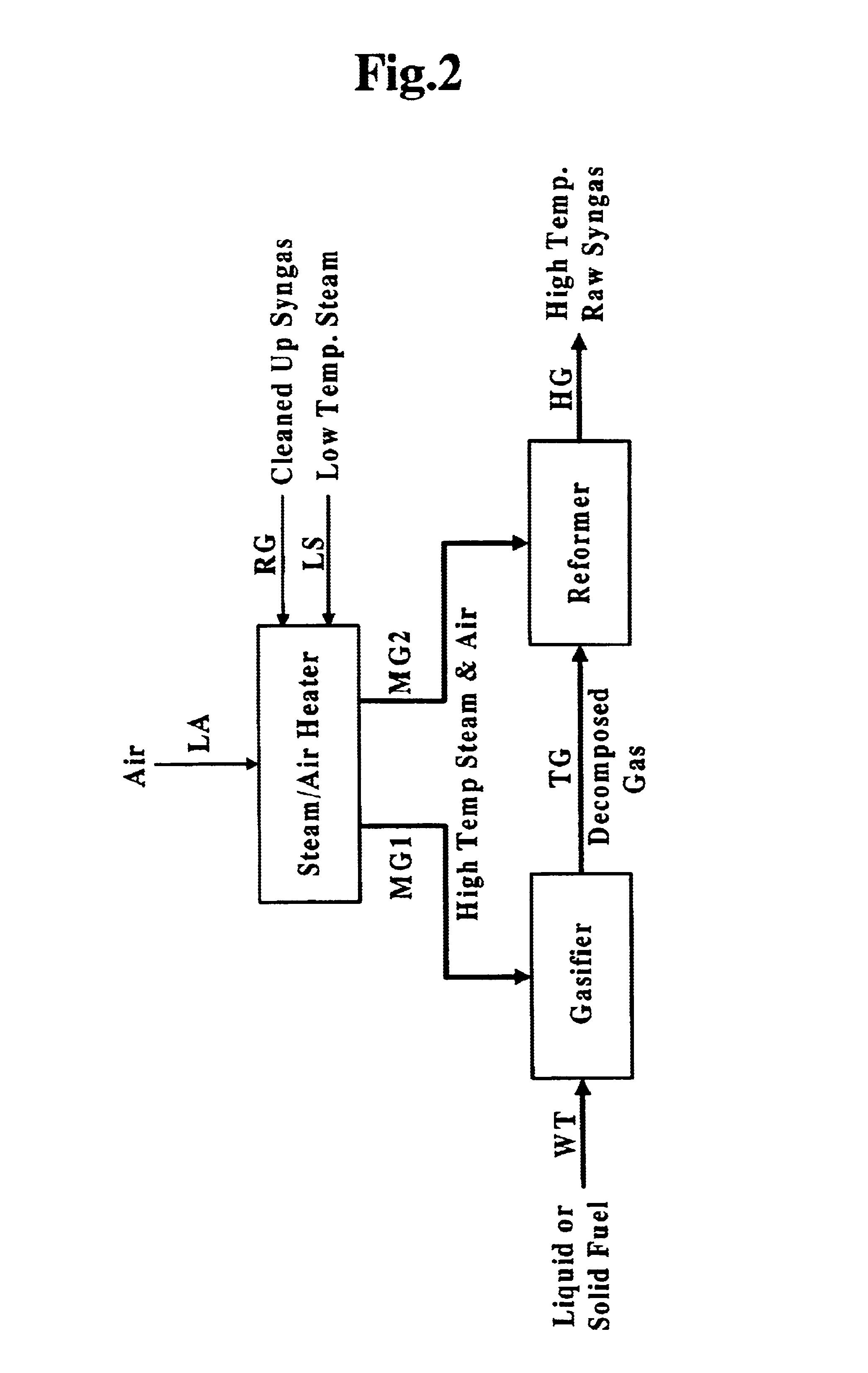
According to the present invention, the high-temperature steam and air are introduced into at least one of the thermal decomposition area and the reforming area, so that the air takes an exothermic reaction with the decomposed gas whereas the steam takes an endothermic reaction with carbon compound in the decomposed gas. Introduction of an appropriate ratio of the air and steam thereinto allows a desired reaction to be carried out between the decomposed gas and the air or steam, whereby a relatively high quality raw syngas can be produced.
The aforementioned high-temperature mixture or high-temperature steam and air are introduced into either or both of the thermal decomposition area and the reforming area, so that the high-temperature steam and air react upon the liquid or solid fuel as well as upon the carbon compound in the thermal decomposed gas. The thermal decomposed gas is reformed into a raw syngas containing hydrocarbon, hydrogen and carbon monoxide to be fed to a cooling device and a gas treatment device as a high-temperature raw syngas. Preferably, the sensible heat of the high-temperature syngas is used in the cooling device to evaporate water to be the low-temperature steam or to heat steam produced by a steam generator. Thus, the thermal efficiency in the whole system can be improved by effective heat recovery of the sensible heat of the high-temperature syngas.
The cleaned up or refined syngas produced by the gasifying apparatus of the present invention can be supplied as a main fuel to a combustion device of a combustion facility or engine, such as a burner or a combustor. If the heat energy of the combustion device is used to drive a power generator, the electrical energy can be supplied thereform to an instruments or facilities out of the system. For example, if waste or refuse of a building or a plant is used as the liquid or solid fuel, the gasifying apparatus can be operatively associated with a gas turbine or a power generator so as to constitute a relatively compact co-generation system.

Problems solved by technology

In such a type of gasification system, a large amount of sensible heat of the thermal decomposed gas is lost in the scrubbing and cracking devices, so that the thermal efficiency of the whole system is degraded.
However, it is found out that the heat of reaction required for the steam reforming reaction of the thermal decomposed gas cannot be sufficiently obtained even if the high-temperature steam exceeding 700 deg. C. is fed to the reaction area, and therefore, a simplified method or arrangement is desired to be developed, which can compensate for the shortage of heat required for the aforementioned reforming reaction.

Method used


Image

  • Apparatus and method for gasifying liquid or solid fuel
  • Apparatus and method for gasifying liquid or solid fuel
  • Apparatus and method for gasifying liquid or solid fuel

Examples


Embodiment Construction

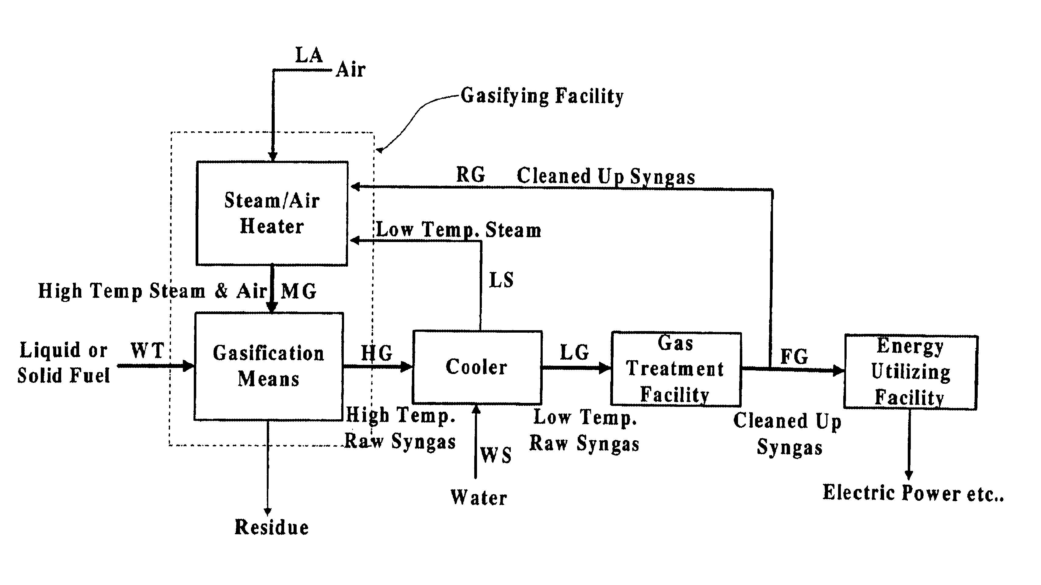
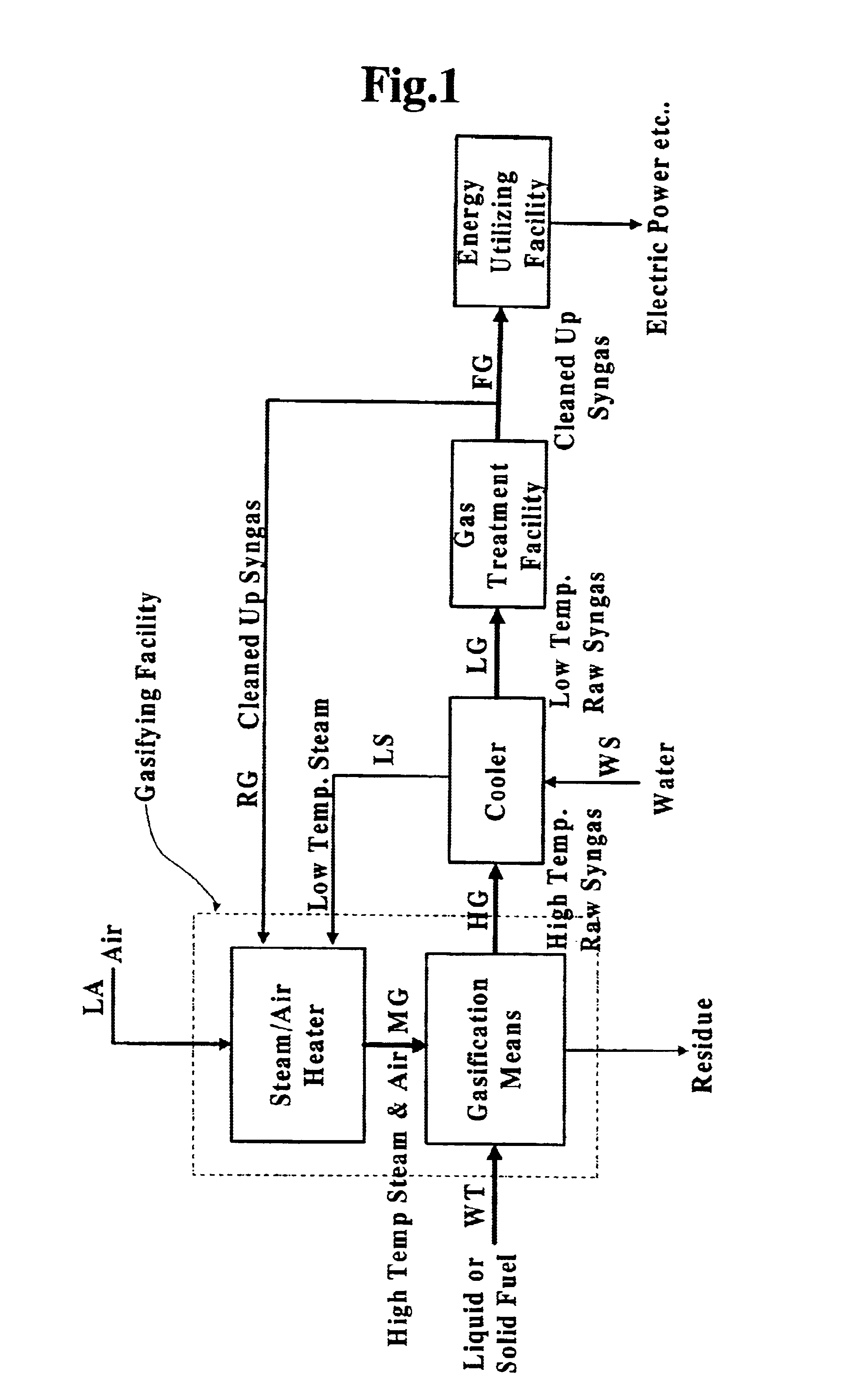
FIG. 1 is a system flow diagram generally illustrating an arrangement of a preferred embodiment of solid or liquid fuel gasifying apparatus according to the present invention.

The solid or liquid fuel gasifying apparatus comprises gasificaition means for thermally decomposing a liquid or solid fuel, a gas cooler for cooling a high-temperature raw syngas delivered from the gasificaition means, a gas treatment facility for cleaning up or refining the raw syngas, and a steam / air heating device for feeding an amount of high-temperature steam and air to the thermal decomposition area or reforming area in the gasificaition means. A gasifying facility is defined by the gasificaition means and the steam / air heating device. The liquid or solid fuel, such as waste, coal or the like, is charged into the gasificaition means by fuel supply means WT. The low-temperature steam and air are heated by the steam / air heating device up to a temperature equal to or higher than 700 deg. C., preferably high...


PUM


Abstract

A gasifying apparatus comprises a gasifier, a reformer and a heating device. The gasifier produces a thermal decomposed gas with use of a thermal decomposition reaction of a liquid or solid fuel such as waste or coal, and the heating device heats a low-temperature steam and air so as to be a high-temperature steam and air, which have a temperature equal to or higher than 700 deg. C. The gasifying apparatus has feeding means including fluid passages for feeding the high-temperature steam and air to the gasifier and the reformer. In a thermal decomposition area of the gasifier, the liquid or solid fuel is thermally decomposed to produce the thermal decomposed gas with sensible heat of the high-temperature steam and air and with the heat generated by an exothermic oxidation reaction between the high-temperature air and the liquid or solid fuel. In the reformer, the thermal decomposed gas is reformed in the existence of the high-temperature steam so as to be a high-temperature syngas. The steam reforming reaction of the liquid or solid fuel is carried out with an exothermic reaction between the high-temperature air and hydrocarbon contained in the thermal decomposed gas and with an endothermic reaction between the hydrocarbon and the high-temperature steam.

Description

TECHNICAL FIELD OF THE INVENTIONThe present invention relates to an apparatus and method for gasifying liquid or solid fuel and, more specifically, to such an apparatus and method for producing a relatively high-quality syngas by gasifying liquid or solid fuel, such as waste, coal, biomass fuel, heavy oil and so forth with a thermal decomposition reaction.BACKGROUND OF THE INVENTIONThere is known a solid-fuel gasifying system, in which a waste such as waste plastic, sludge, shredder dust, municipal refuse, or a solid fuel such as coal is introduced into a thermal decomposition furnace. The solid fuel is thermally decomposed into a thermal decomposed gas or pyrolysis gas within a high-temperature reducing atmosphere of less or low oxygen concentration. A variety of combustion furnaces or incinerators may be generally used as a the thermal decomposition furnace, such as a waste gasification melting furnace, a coal gasification furnace, a rotary kiln type of thermal decomposition furna...

Claims


Application Information

Patent Timeline
IPC IPC(8): C01B3/32C01B3/00C01B3/36C10J3/16C10J3/02C10J3/26
CPCC01B3/32C01B3/36C10J3/16C10J3/26C10K3/006C10J2300/0956C10J2300/1215C10J2300/1853C10J2300/1869C10J2300/1884C10J2300/1892C10J2300/0976C10J2300/1253C10J2300/1671
Inventor YOSHIKAWA, KUNIOYASUDA, TSUTOMUSAKAI, MASARUISHII, TORU
Owner NIPPON FURNANCE IND KAISHA
Learn More