

Method and apparatus for regenerating an iron-based Fischer-Tropsch catalyst
a technology of iron-based fischer-tropsch catalyst and method, which is applied in the direction of vacuum distillation separation, separation process, other chemical processes, etc., can solve the problems of increasing catalyst cost, inhibiting the activity of catalyst, and procedures described in these patents, and not providing wax- and contaminant-free catalysts
Active Publication Date: 2005-01-04
RES USA LLC
View PDF23 Cites 105 Cited by
- Summary
- Abstract
- Description
- Claims
- Application Information
AI Technical Summary
Benefits of technology
Another aspect of the present method is that a low concentration of catalyst in a slurry can be accommodated. Wax in the slurry is removed from the system as solvent is added to replace the removed wax, whereby slurry levels are maintained.
Yet another aspect of the present invention is that the catalyst is not subjected to pumps or other mechanical devices which could cause attrition of the catalyst particles.
Problems solved by technology
Thus, it is well-known that build up or growth on the surface of the catalyst tends to inhibit the activity of the catalyst.
In either case, downtime results and in the former, significantly increased catalyst costs are incurred.”
The procedures described in these patents, however, do not provide a wax- and contaminant-free catalyst.
The difficulty in oxidizing the precipitated iron catalyst is, however, preventing overheating and sintering of the catalyst.
This method, however, is not applicable to a precipitated iron catalyst.
Method used
View moreImage
Smart ImageViewing Examples

Examples
example 1
is presented herein to show one embodiment of the invention and should not be construed as a limitation of the invention. Different gases, solvents, pressures and temperatures can be chosen by one skilled in the art to optimize the different steps of the invention. Solvents other than hexane such as hexene, heptane, heptene, tetrahydrofuran and Fischer-Tropsch naphtha can be used. Also, the novel method of wax extraction described herein can be applied to any wax-laden Fischer-Tropsch catalyst, including cobalt and ruthenium.
Login to View More PUM
| Property | Measurement | Unit |
|---|---|---|
| Temperature | aaaaa | aaaaa |
| Temperature | aaaaa | aaaaa |
| Temperature | aaaaa | aaaaa |
Abstract
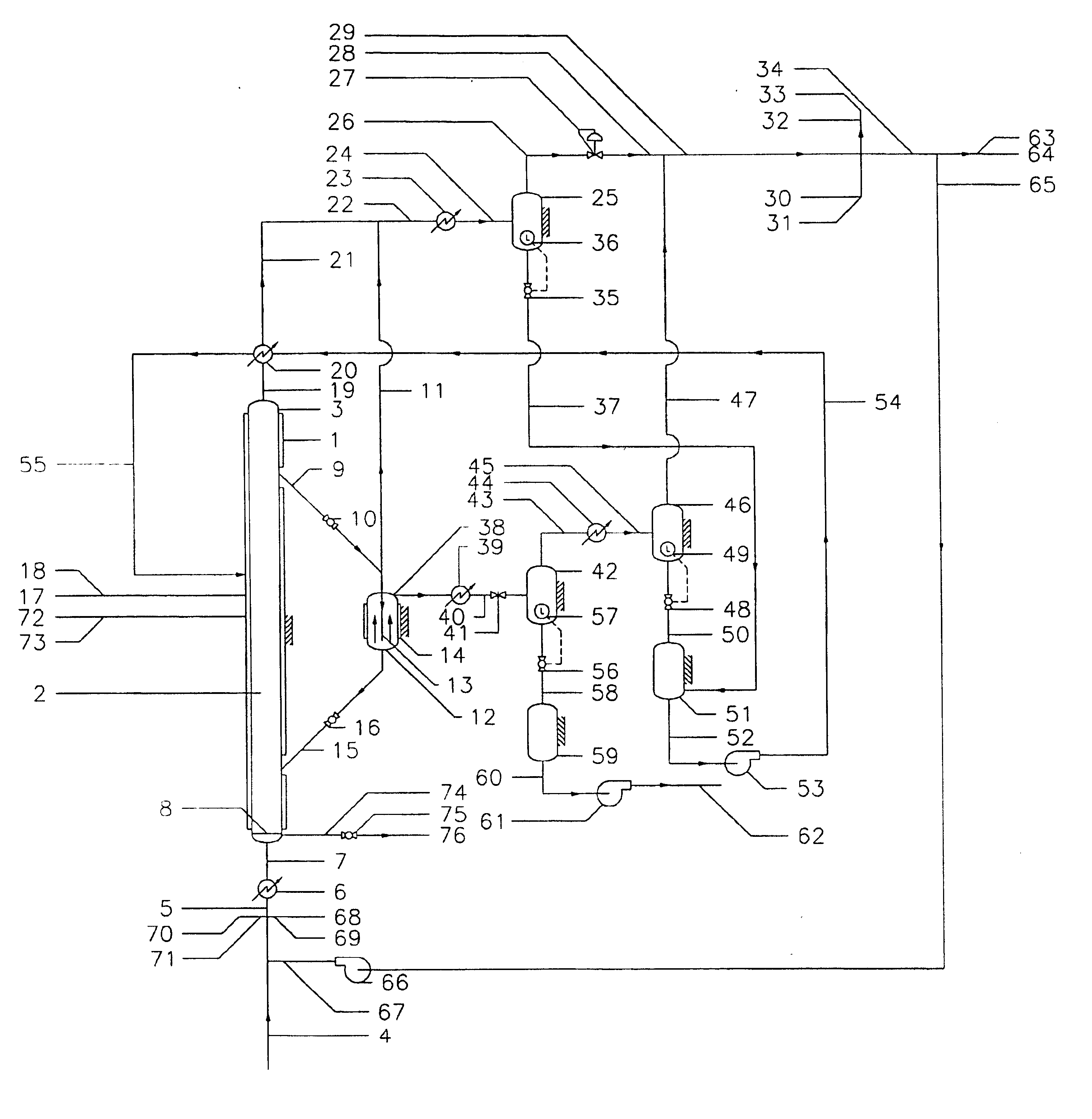
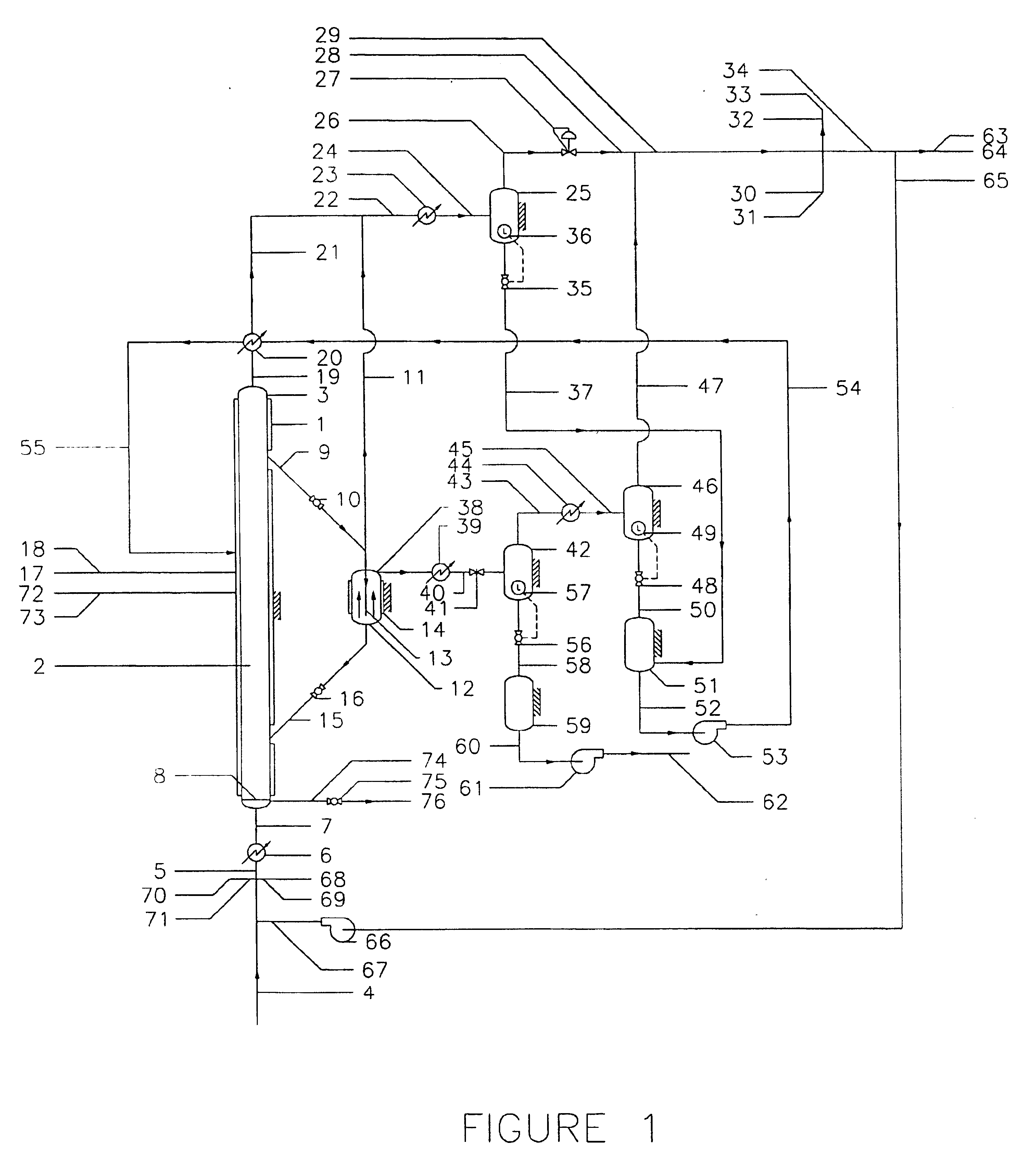
Solvent extraction is used to remove wax and contaminants from an iron-based Fischer-Tropsch catalyst in a natural circulation continuous-flow system. The wax-free catalyst is then subjected to controlled oxidation to convert the iron to its initial oxidized state, Fe2O3. Reactivation of the oxide catalyst precursor is carried out by addition of synthesis gas.
Description
FIELD OF INVENTIONThe present invention relates to the production of liquids and waxes from synthesis gas using the Fischer-Tropsch (FT) process, and more particularly to regenerating an iron-based FT catalyst that has become deactivated due to buildup of contaminants on the surface of the catalyst.BACKGROUND OF THE INVENTIONThe low costs associated with iron-based FT catalysts have heretofore been a major factor in the lack of development of methods for regenerating these catalysts. However, increasing concerns over disposal of industrial wastes in landfills from both economic and environmental standpoints have created a need for improved methods for recycling spent catalysts —even for the low-cost catalysts. When a catalyst is employed in a slurry reactor, disposal of spent catalyst can be challenging. Some methods have been proposed which rejuvenate iron-based catalysts for a short period of time, but an economical method is needed for returning the catalyst back to its initial o...
Claims
Login to View More Application Information
Patent Timeline
 IPC IPC(8): B01J23/90B01J23/94B01J38/00B01J38/14B01J38/50C10G2/00B01J23/78B01J23/745B01J23/76B01J23/96B01J38/56B01J38/52
CPCB01D3/10B01J23/78B01J23/94B01J38/14B01J38/50B01J38/58B01J38/68C10G2/332B01J8/22C10G2300/703B01J23/745B01J23/96B01J38/52B01J38/56B01J2219/00006
InventorDEMIREL, BELMABOHN, MARK S.BENHAM, CHARLES B.SIEBARTH, JAMES E.IBSEN, MARK D.
OwnerRES USA LLC