It is apparent that in such a complex and delicate production process, various problems, failures or defects, may arise or develop during each step, or from the serial combination of steps.
Because of the stringent quality requirements, any problem which is not discovered in time may result in the rejection of a single wafer, or of the whole lot.
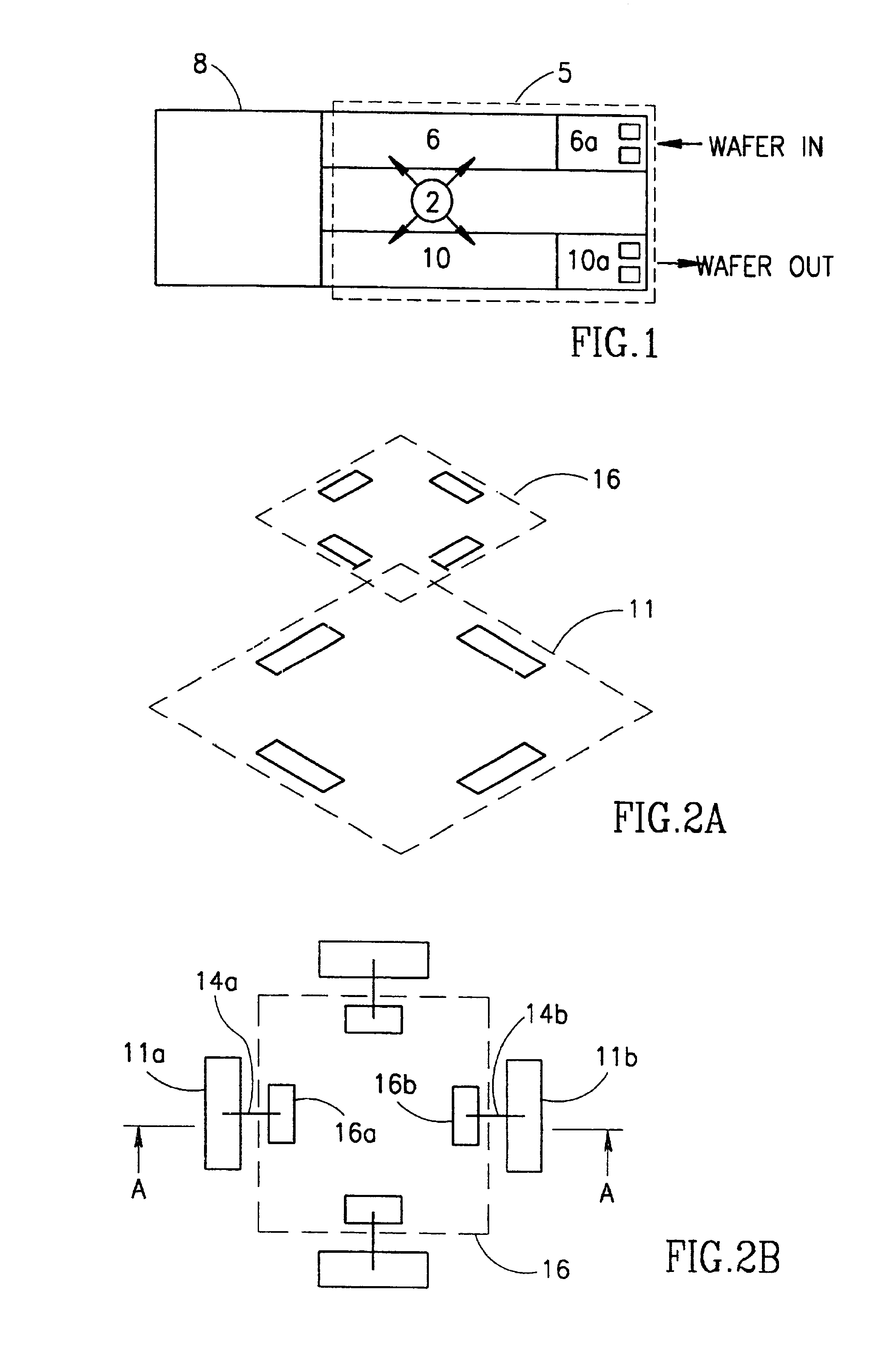
A wafer cannot be taken out of the photocluster for measurement or inspecting before the process is completed and the wafer arrives at the cassette
station 10b. As a result, any
process control based on measuring processed wafers cannot provide ‘real time’ process malfunction detection.
However, examination of the prior art, insofar as known to us, indicates that no such
monitoring and control methods and / or systems exist.
The shrinking dimensions of the wafer's features increases the demands on
overlay accuracy.
This break may even take a few hours.
In some cases this may take hours, or more.2) They result in a waste of wafers, and / or lots of wafers because of this post-process response.
Such an error source cannot be corrected later since the error varies for each lot.
For this reason it is important to have the feedback within the
time frame of the first wafer which cannot be obtained using a ‘stand-alone’ tool.4) The
overlay sampling frequency is limited due to
contamination restrictions and additional expensive time needed for extra handling and measurements.5)
Throughput of the photolithography process is reduced as a result of the post-process
overlay detection and the long response-time, as well as of the reduced sampling frequency mentioned in (3).6) These stand-alone systems require additional expensive foot-print and labor in the Fab.7) The microlithography tools are the “
bottle neck” in the semiconductors production process and they are the most expensive tools in the FAB.
Their partial utilization due to late off-line measurements reduces drastically overall equipment efficiency in the Fab.
This break may take even few hours.
In particular, no integrated automatic ADI
system is commercially available at the moment.
These defects can be, for example, poor
spinning during
coating, poor development, scum, non-attached PR (‘lifting’), and / or edge beads.
These defects can be, e.g., shorts between conducting lines, and focus failures of the
stepper.
ADI conducted by humans has several disadvantages:(a) It is tedious and requires great concentration to locate pattern discrepancies in repetitive and complex circuits.(b) The results are not uniform with respect to each inspector as well as between different inspectors.
This point becomes crucial when considering the increased importance of inspecting at times when the wafer features become more and more delicate due to the continuous shrinking of the wafer's features.(c) It is not a consistent means for
statistical analysis and for measuring
process quality due to non-repetitive results.(d) Additional costs due to the labor.(e) Non objective inspecting, neither in defects identification nor in the specific action which should take place once a specific defect is identified.(f) Fluctuating
throughput results, among other things, in difficulties to determine sampling frequency.(g) Manual inspecting is also done off-line and therefore suffers from all the same aforementioned disadvantages of ‘stand-alone’ systems.
To complete the picture, it should be noted that two automatic optical inspection (AOI) methods for defect detection are known, but their high cost and low
throughput limit their use in actual production.(i) Absolute methods—illuminating a wafer at a predetermined angle (“
grazing”) and collecting the reflected
signal from the wafer's plane.
None of the available inspecting tools samples each wafer, but only several wafer in a lot.
Moreover, the lack of such inspecting systems prevents any option for automatic and tight feedback or
closed loop control over the
lithography process.
Thus, any serious attempt for establishing or even improving the
process control around the photolithography process is prevented, or at least is met with crucial obstacles due to the lack of such method(s) and systems.
This break may take even few hours.
It is clear, as was noted before with respect to overlay
metrology and inspecting tools, that since all CD
metrology systems are ‘stand-alone’ tools, they suffer from the same drawbacks as discussed before.
Moreover, especially in the case of CD measurement, the results, e.g.,
line width, give a limited ability to correlate the measurement to any specific cause.
However a certain increment in the risk is introduced because a total lot may be lost.
Satisfactory results will be a basis for the set up conditions of the lot, whereas unsatisfactory results will cause another wafer to be exposed with corrections for the
exposure conditions.
The over all sequence of a “send ahead wafer” control can take many hours while valuable utility time of the production tools, as well as the production lot, may be lost.
However, this is the most time-consuming method.
The drawbacks of these methods, when conducted with ‘stand-alone’ overlay and OCD tools, are that they are time and effort consuming and they usually do not respond directly for certain causes, or do not reveal any problematic sources.
“Stand-alone” monitoring and
process control systems do not meet these stringent requirements, and apparently cannot be used as an integrated
system.
Moreover, no such integrated
system is now available on the market.

