Compound/curvilinear immiscible liquid separator apparatus and method

a liquid separator and immiscible technology, applied in the direction of liquid degasification, separation process, filtration separation, etc., can solve the problems of reducing the efficiency of liquid separation, so as to improve increase the agglomeration of low-density liquid particles. , the effect of increasing the efficiency of separating substances

Inactive Publication Date: 2005-01-18
APT INC
View PDF39 Cites 14 Cited by
  • Summary
  • Abstract
  • Description
  • Claims
  • Application Information

AI Technical Summary

Benefits of technology

Accordingly, it is a principal object of the invention to provide a separator for separating a liquid-liquid-gas mixture of immiscible substances having increased efficiency for separating finely divided liquid particles, such as oil pumped from a well and mixed with brine water.
It is another object of the invention to apply centripetal, centrifugal, and rotational forces in a laminar flow of immiscible substances for increased efficiency in separating the substances.
It is a further object of the invention to provide a separator for immiscible fluids which uses a chimney effect provided by gases evolved during the separation to increase agglomeration of low density liquid particles by nucleation to improve the efficiency of the separation.

Problems solved by technology

The above processes require large storage facilities, which are extremely expensive and hazardous to operate, such as the electrostatic separation process.
This turbulence within fluid flow renders Stokes' law inapplicable.
Technologies used on the market today do not address the inapplicability of Stokes' law to a moving flow of water.
Such incomplete solutions to the oil-water separation problem yield less than optimal removal of oil from the oil-water mixture.
Other approaches employing various filters and the like have a known tendency to clog and become blocked with sediment and are very costly to operate.
This kind of system is very costly to maintain and operate.
Likewise, an electrostatic system's use of high impressed voltage across plate anodes to cause ionic changes for particle agglomeration requires high energy levels, and is hazardous when vapors occur.
None of the foregoing patents use a heating element to apply a thermal gradient.

Method used


Image

  • Compound/curvilinear immiscible liquid separator apparatus and method
  • Compound/curvilinear immiscible liquid separator apparatus and method
  • Compound/curvilinear immiscible liquid separator apparatus and method

Examples


Embodiment Construction

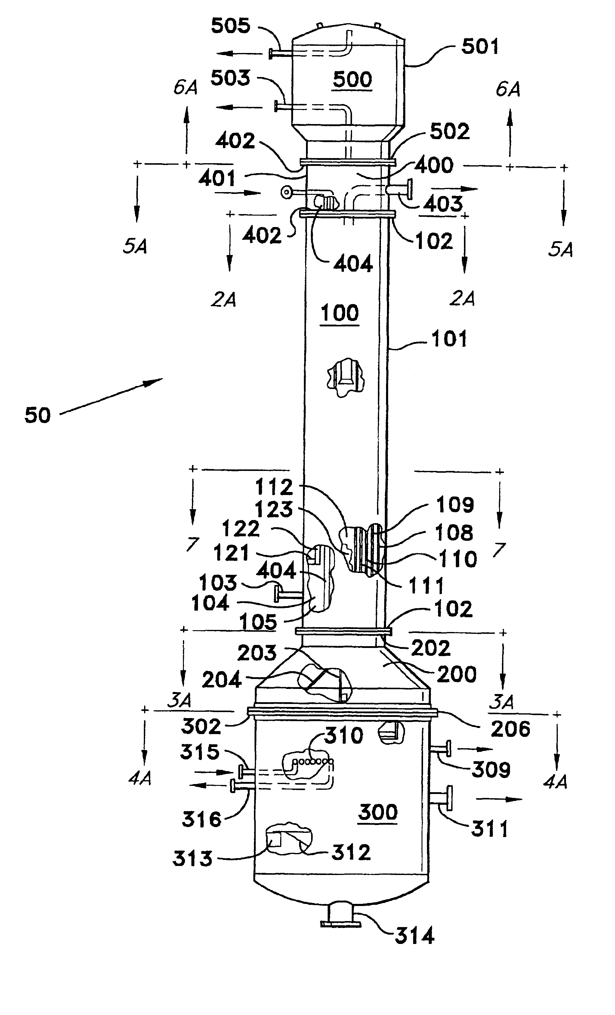
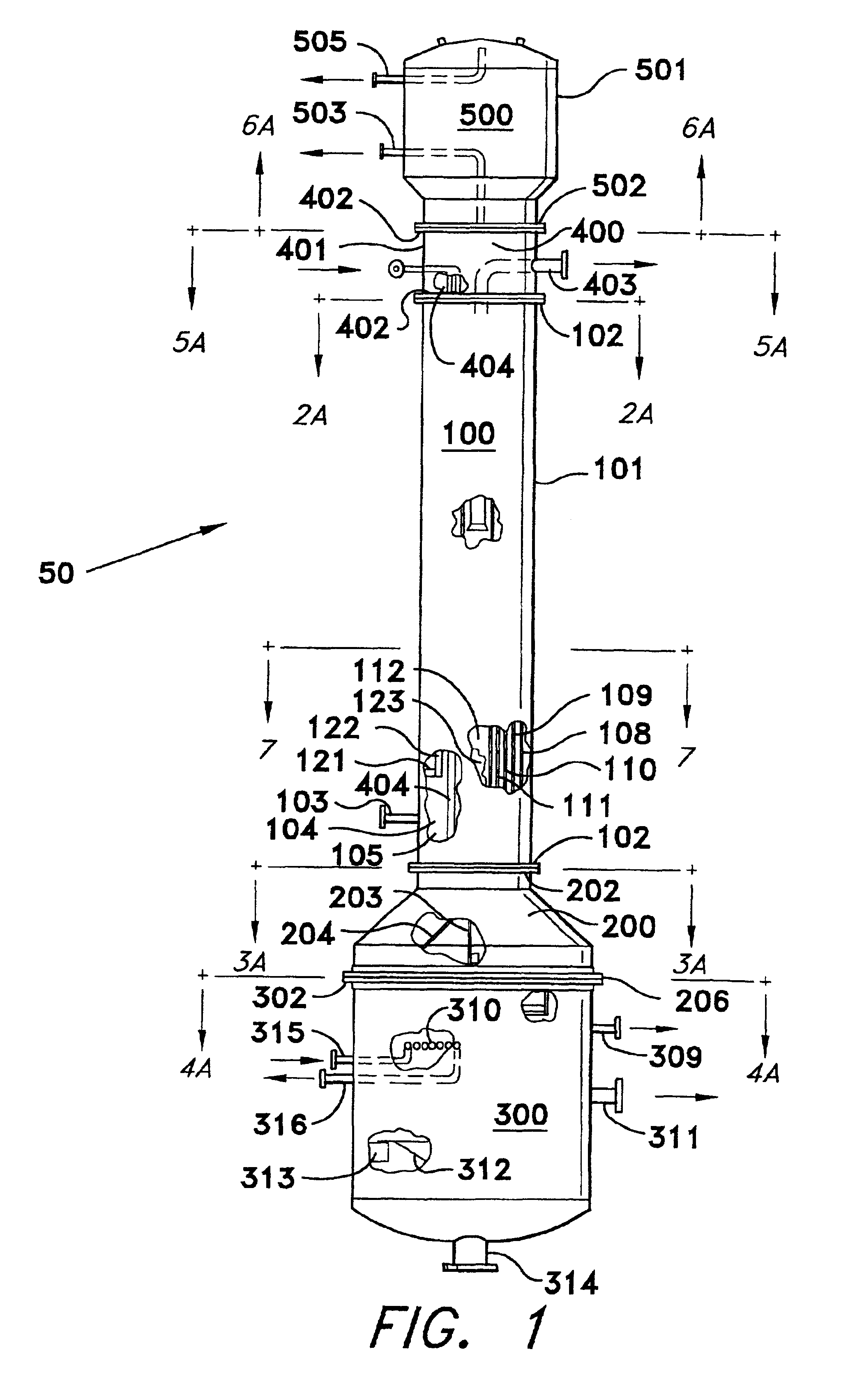
The present invention is a compound / curvilinear immiscible liquid separator, designated generally as 50 in FIG. 1. The device is designed to use known processes and methods involving particle dynamics, agglomeration kinetics, particle translation within a fluid, centrifugal and centripetal forces exerted on a particle of given mass moving in a curved plane, and circulatory fluid motions associated with temperature gradients and defined as convection flow. For the purpose of this description, the primary emphasis is on the separation of immiscible liquids of varying densities within a carrying fluid, the carrying fluid being water (brine water) with a specific gravity of 1.0 or greater at standard atmosphere conditions.

The device 50 shown in FIG. 1 is designed for constant pressurized operating conditions with temperature being controlled within different sections of this apparatus to accelerate immiscible liquid separation of liquid with different densities. Fluid flow through the a...


PUM

PropertyMeasurementUnit
dihedral angleaaaaaaaaaa

Abstract

The compound/curvilinear immiscible liquid separator has a separator section with an outer, elongated, cylindrical shell aligned vertically opening into an upper transition section and vapor dome at the top and a lower transition section and solid/heavy crude containment section at the bottom. A center column is disposed in the axial center of the separator section and a plurality of serially connected curved plates are disposed between the outer shell and center column to define an elongated curvilinear flow path having reverse flow pathways. An oil-water-gas mixture is introduced into the separator section under pressure past heating coils and through the curvilinear path, the lighter density oil entering and being removed from the top of the center column, and heavier sludge and brine collecting in the containment section. Gases bubble up through the center column and are removed from the vapor dome.

Description

BACKGROUND OF THE INVENTION1. Field of the InventionThe present invention relates to a curvilinear compound separator apparatus and method for separating multiple immiscible liquids, gases, and rigid particles of varying densities from liquid mixtures that are in motion within a temperature and pressure controlled environment. This unique device and method utilizes the particle kinetic energy within a moving stream and the interaction of these particles within the controlled flow pathway to separate immiscible substances. The principles of particle dynamics (forces of buoyancy, weight, drag, and particle translation with respect to the time within the controlled environment (time dependent motion)) are applied to cause the accelerated movement and separation of immiscible particles.2. Description of Related ArtIt is desired to find an effective way to recover petroleum products from brine. In particular, in the field of crude oil production, it is required to have an accelerated liq...

Claims


Application Information

Patent Timeline
Patent Type & Authority Patents(United States)
IPC IPC(8): B01D17/00B01D19/00
CPCB01D17/005B01D19/001B01D19/0042B01D17/0208B01D17/0211B01D17/0217
Inventor GREENE, BOYD B.GREENE, HELEN C.
Owner APT INC
Why Eureka
Try Eureka