

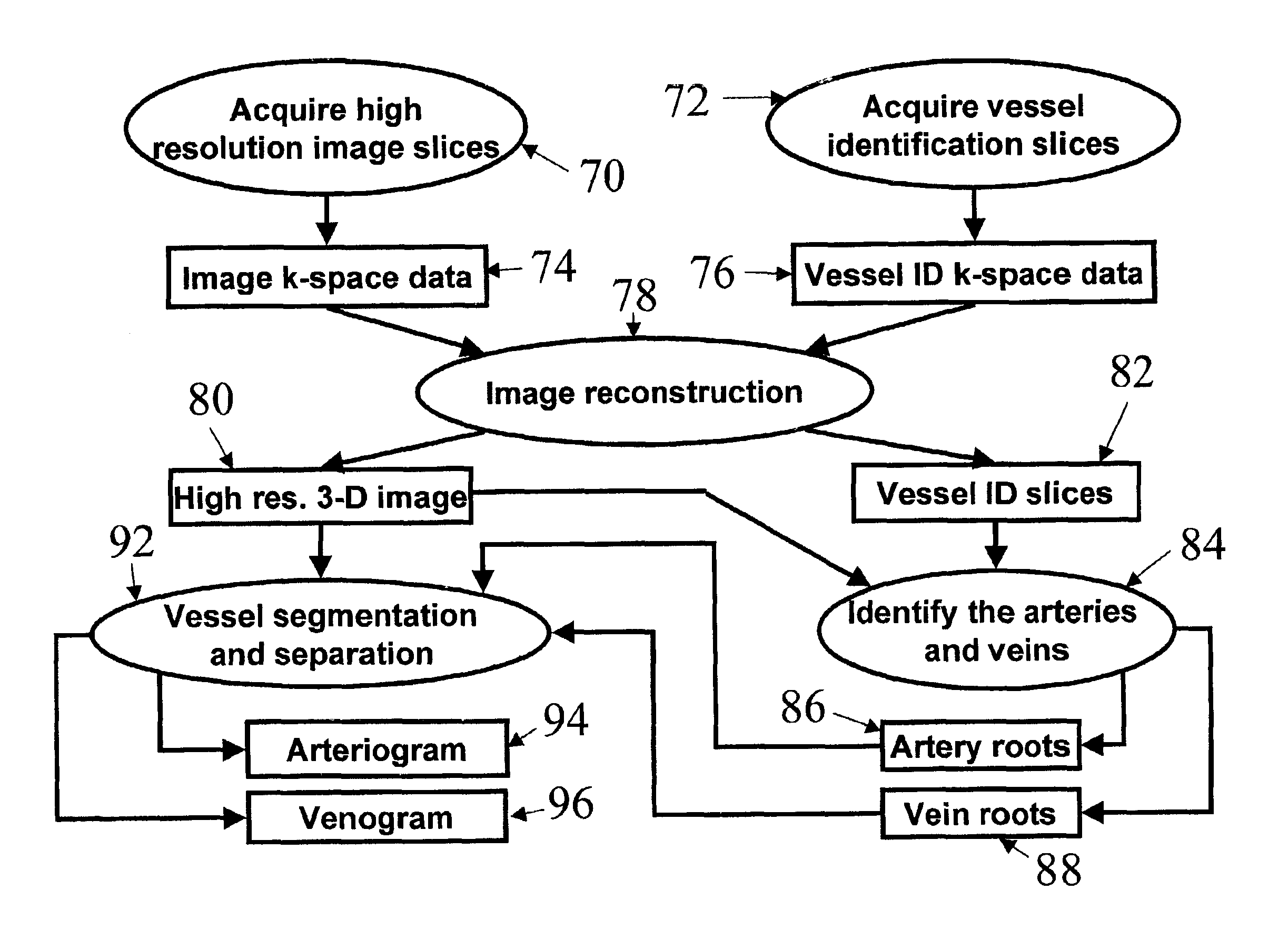
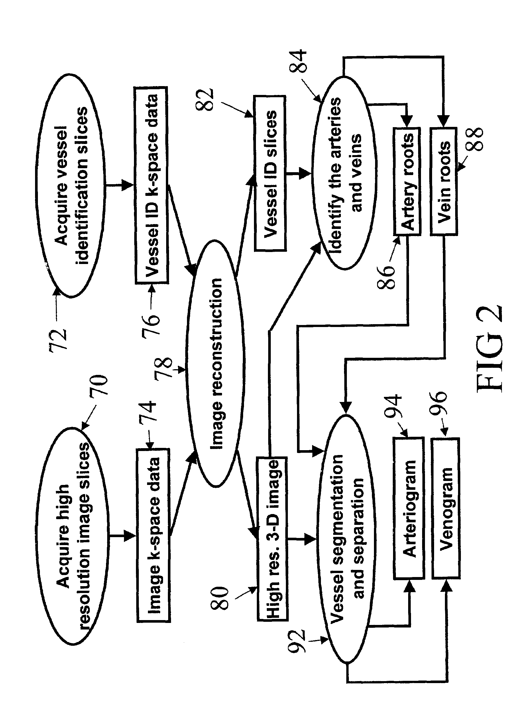
Automatic vessel indentification for angiographic screening
a technology of automatic indentification and angiography, applied in the field of magnetic resonance angiography, can solve the problems of misleading gray scales, complicated analysis and interpretation of unprocessed gray scale mra images, and increase the difficulty of mra data acquisition, so as to improve the specific absorption ratio (sar) level, improve the scan time, and improve the effect of vascular segmentation and separation
- Summary
- Abstract
- Description
- Claims
- Application Information
AI Technical Summary
Benefits of technology
Problems solved by technology
Method used
Image

Examples
Embodiment Construction
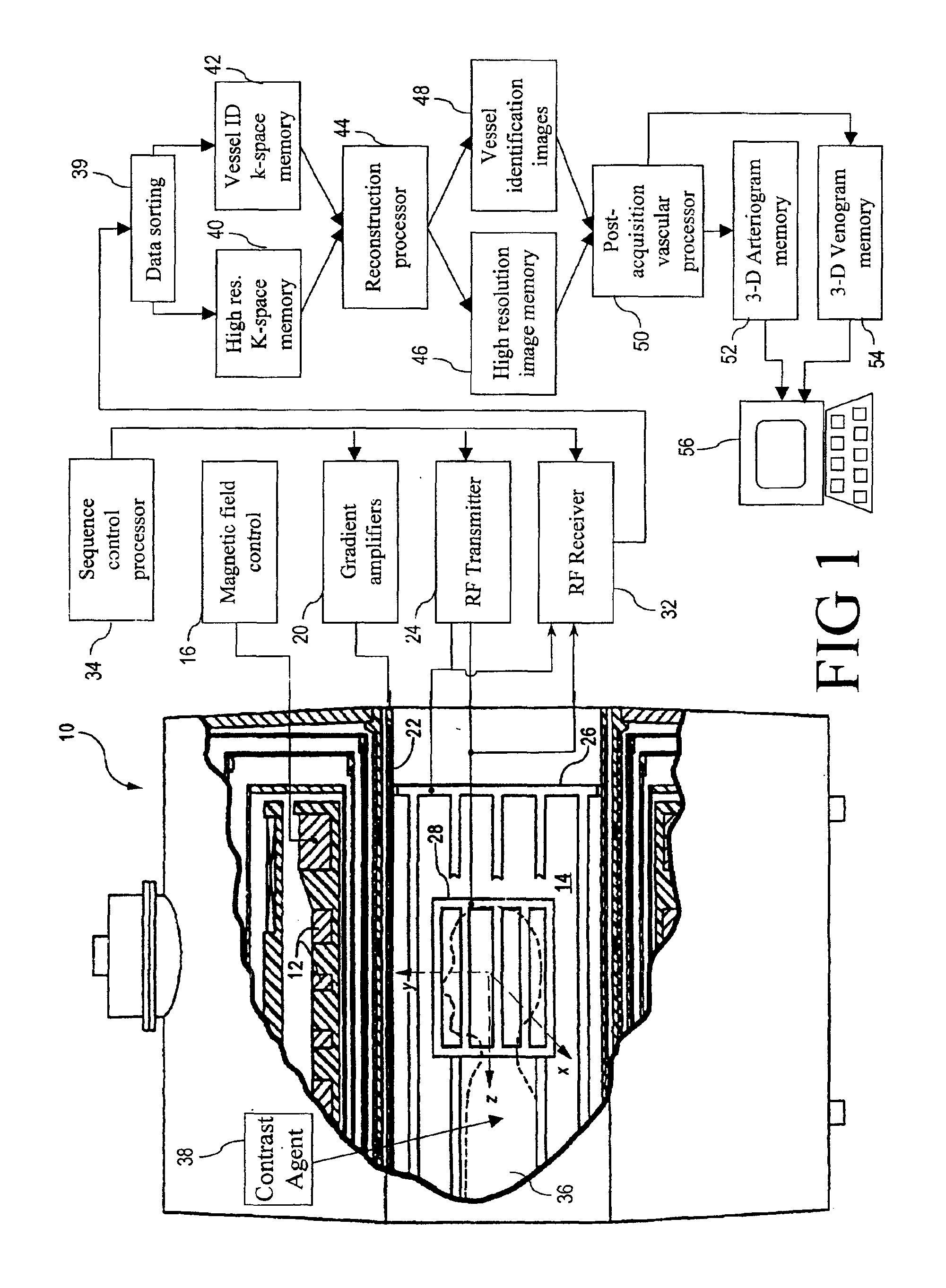
With reference to FIG. 1, a magnetic resonance imaging (MRI) scanner 10 includes superconducting or resistive magnets 12 that create a substantially uniform, temporally constant main magnetic field B0 along a z-axis through an examination region 14. Although a bore-type magnet is illustrated in FIG. 1, the present invention is equally applicable to open magnet systems, vertical field systems, and other types of MRI scanners. The magnets 12 are controlled by a main magnetic field control 16. Imaging is conducted by executing a magnetic resonance (MR) sequence with the subject being imaged, e.g. a patient 36 in a magnetic resonance angiography (MRA) session, placed at least partially within the examination region 14, typically with the region of interest at the isocenter.
The magnetic resonance sequence entails a series of RF and magnetic field gradient pulses that are applied to the subject to invert or excite magnetic spins, induce magnetic resonance, refocus magnetic resonance, mani...
PUM
 Abstract
Description
Claims
Application Information