

Pulsed carbon plasma apparatus
a plasma apparatus and plasma technology, applied in plasma techniques, vacuum evaporation coatings, nuclear engineering, etc., can solve the problems of insufficient reliability of arc striking devices, inability to deposit coatings on extended objects, and high non-uniform thickness of coatings, so as to improve the life and operating performance of tools and machine parts, the effect of high thickness uniformity
- Summary
- Abstract
- Description
- Claims
- Application Information
AI Technical Summary
Benefits of technology
Problems solved by technology
Method used
Image


Examples
Embodiment Construction
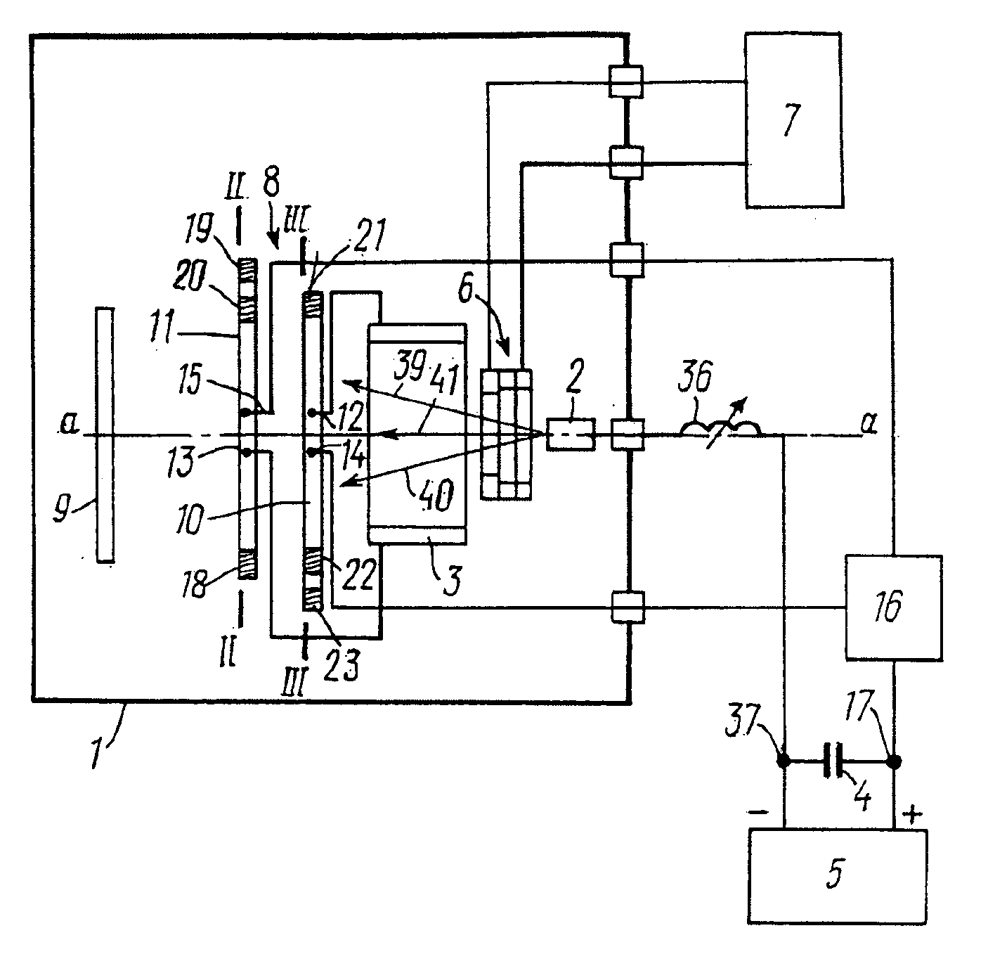
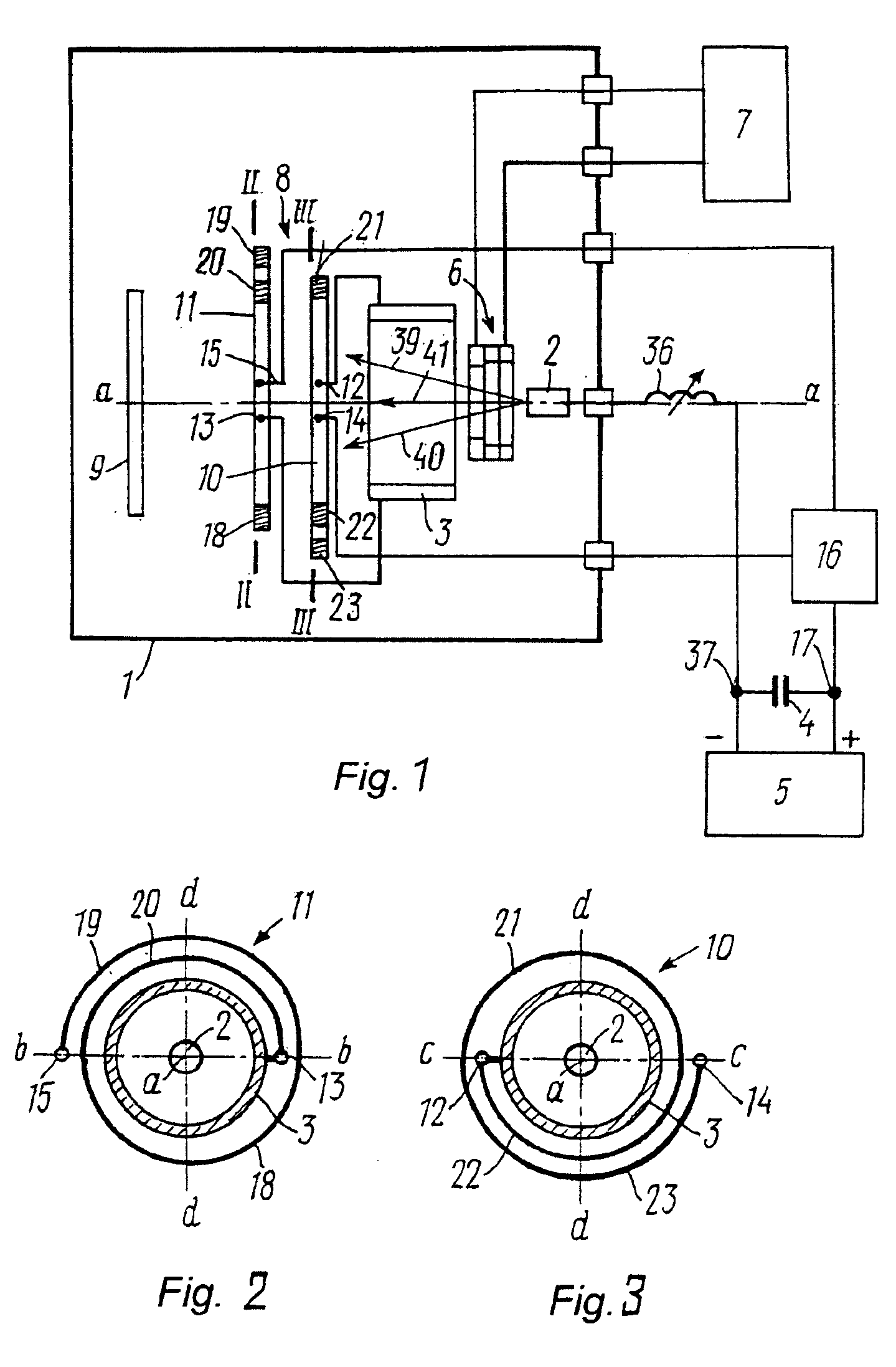
The pulsed carbon plasma apparatus of the invention comprises a carbon plasma flow scanning device having at least one pair of deflecting coils, which, in a scanning plane, have a different number of turns on opposite sides; a consumable graphite cathode and an anode, both accommodated in a vacuum chamber and having a common geometrical axis, the consumable graphite cathode and the anode being electrically coupled to a capacitive storage shunted to a dc charger; and an arc striking device disposed in the vacuum chamber and connected to an initiation unit. The deflecting coils are arranged in the vacuum chamber so that the geometrical axes of the deflecting coils are aligned with the geometrical axis of the cathode and the anode, and wound in one direction, one output of each coil in the pair of deflecting coils being connected to the anode, and another output being connected, via a controlled switch, to a positive output of the capacitive storage. Each of the deflecting coils compri...
PUM
| Property | Measurement | Unit |
|---|---|---|
| inductance | aaaaa | aaaaa |
| shape | aaaaa | aaaaa |
| biological compatibility | aaaaa | aaaaa |
Abstract
Description
Claims
Application Information