
Exhaust emission aftertreatment

Inactive Publication Date: 2005-02-22
GM GLOBAL TECH OPERATIONS LLC
View PDF16 Cites 67 Cited by
  • Summary
  • Abstract
  • Description
  • Claims
  • Application Information

AI Technical Summary

Benefits of technology

The present invention is a method and apparatus for the control of cylinder deactivation in an engine to control the exhaust gas temperature for improved catalytic converter or NOx trap efficiency. More importantly, the deactivated cylinders are used as partial oxidation reactors to generate rich combustion products which can be exhausted to purge and reduce the NOx emissions that are stored in the NOx trap.
Controlling cylinder deactivation in a variable displacement ICE, depends on the ICE bank configuration and firing order. For example, certain V6 and V12 engine configurations allow deactivation of an entire bank of cylinders (one side of the engine), while a line 6 engine may allow three adjacent cylinders to be deactivated. These types of engines may allow favorable grouping of the exhaust flows to enhance aftertreatment performance.
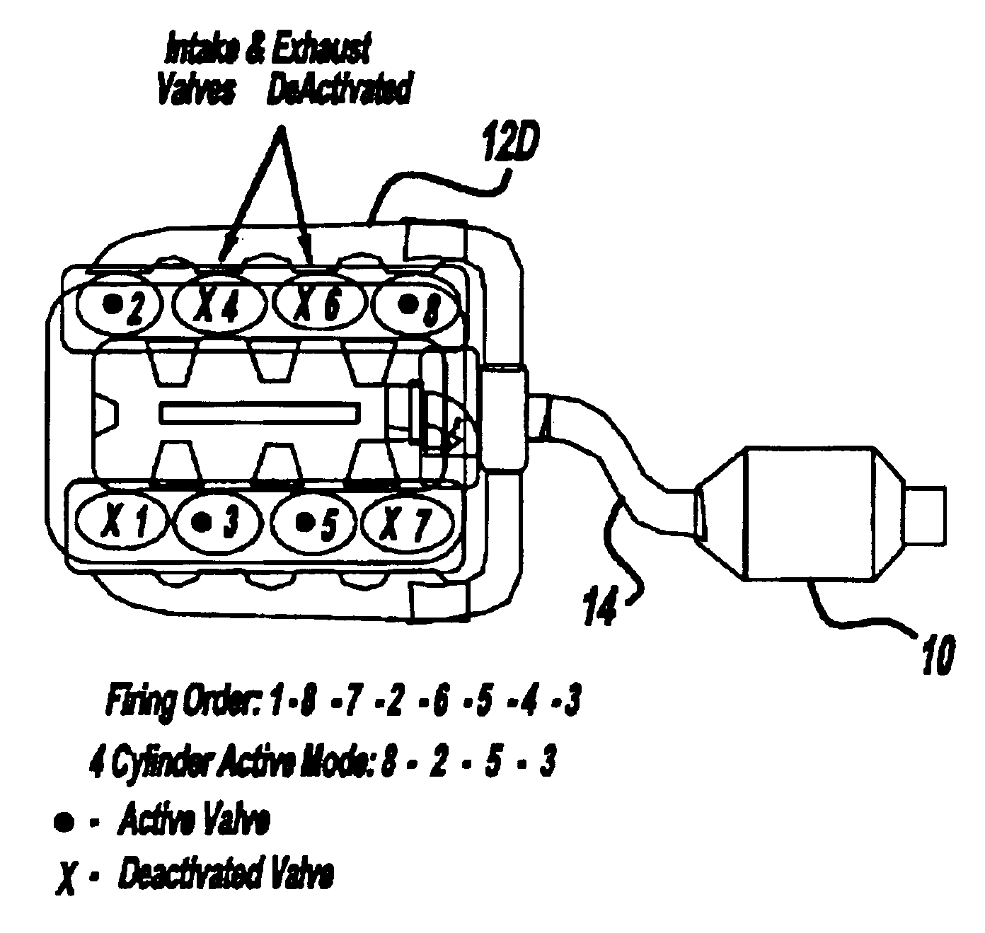
In one embodiment of the present invention, an eight-cylinder diesel (compression ignition) internal combustion engine (ICE) may be operated as a four-cylinder engine by deactivating four cylinders. The cylinders in the preferred embodiment are deactivated by an electro-hydraulic deactivation system using engine oil pressure, controlled by solenoids, to pressurize the locking pins of special engine valve lifters used in an overhead valve engine. With pressure applied, the locking pins allow the lifter to act as a lost motion device to prevent exhaust and intake valve activation.
Cylinder deactivation is used to raise the exhaust gas temperatures and reduce excess exhaust air, richening the air / fuel ratio into the NOx trap. The deactivated cylinders in the present invention may be used as partial oxidation (POx) reactors to provide rich exhaust products to purge the NOx trap.
The POx products are generated by trapping combustion products in the deactivated cylinders and injecting additional fuel during successive cylinder events. The amount and timing of the POx injections can be optimized with engine dynamometer testing to provide the best reductant formation with minimum torque impact. Because the cylinders are closed and the initial contents are known, the additional fuel can be precisely metered to achieve the desired reductant chemistry. The repeated mixing of the combustion products with small amounts of additional burning during successive cycles also improves the air utilization in the cylinder. Air utilization is a limiting factor with direct injected heterogeneous combustion engines, whether they are compression or spark ignited. Unlike intake port injected engines, with homogeneous charge engines the fuel is injected directly into the cylinder and there is little time for fuel vaporization and air mixing. As a result, heterogeneous combustion engines should operate lean of stoichiometric mixtures to avoid high soot, unburned hydrocarbons and carbon particulate emissions. The air utilization limitation is overcome in the deactivated cylinders by allowing the burned cylinder gases and remaining air to be thoroughly mixed, and incrementally burned during several, successive engine cycles.

Problems solved by technology

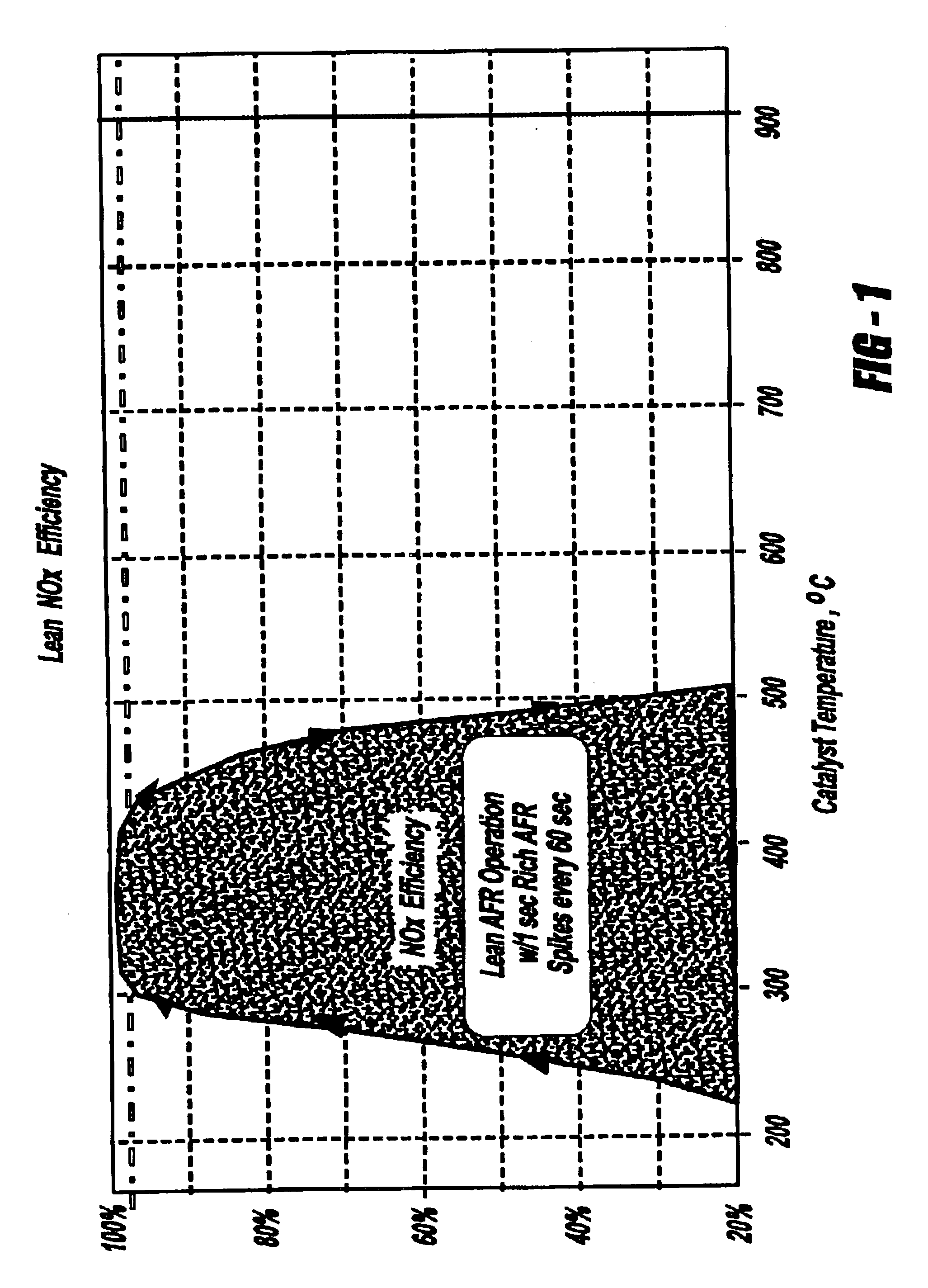
NOx trap performance on diesel engine applications is severely limited by the lower exhaust gas temperatures and the difficulty of providing frequent, rich exhaust mixtures to the catalyst.
A diesel engine's very low exhaust temperatures are the result of very lean operation, and higher compression and expansion ratios.
If vehicle engines are operated on lean mixtures, such as diesel or direct injection gasoline engines having lean stratified operations, the NOx compounds generated may not be sufficiently reduced by traditional three way catalysis.
Therefore, these engines have difficulty meeting the increasingly stringent exhaust emissions regulations.

Method used


Image

  • Exhaust emission aftertreatment
  • Exhaust emission aftertreatment
  • Exhaust emission aftertreatment

Examples


Embodiment Construction

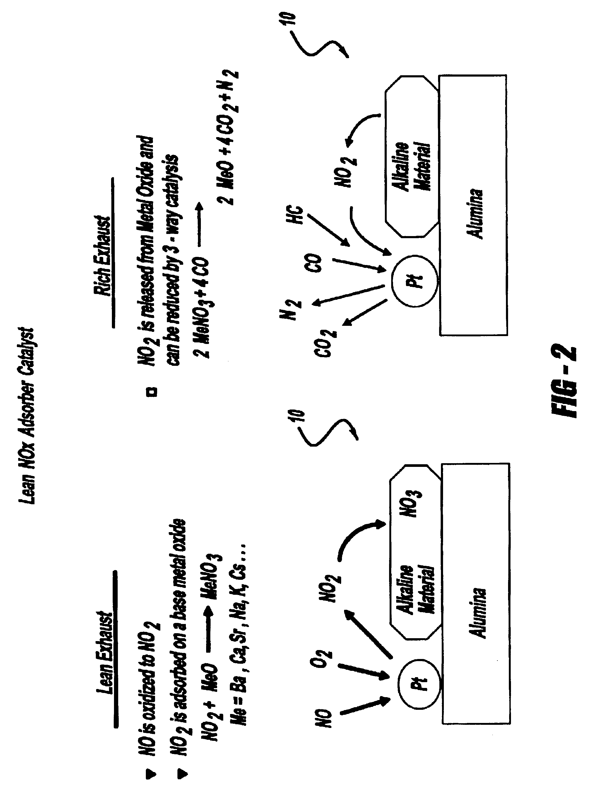
FIG. 2 is a functional diagram of a NOx trap 10 utilizing metal oxides (MeO) as a trapping agent for NOx compounds during lean operating conditions and releasing NOx compounds during rich conditions. The reductant carbon monoxide and hydrocarbons in the relatively rich exhaust stream combine with the NOx and are converted to nitrogen and oxygen.

FIGS. 3A-3E include alternate variable displacement internal combustion engine (ICE) 12 configurations of the present invention. The ICE 12 is preferably a diesel engine but any ICE, including direct injection gasoline ICEs, is within the scope of the present invention. FIG. 3A is a diagrammatic drawing of a variable displacement six cylinder (ICE) 12A. The ICE 12A is coupled to exhaust manifolds 14 and dual NOx traps 10. Any cylinder in the ICE 12A may be deactivated but in the preferred embodiment an entire bank of cylinders (contiguous cylinders) is deactivated during the ICE 12A operation. FIG. 3B, similar to FIG. 3A, is a diagrammatic dr...


PUM


Abstract

An engine control system in a vehicle including a variable displacement internal combustion engine, a controller for controlling the displacement of the variable displacement internal combustion engine, and where the controller operates the variable displacement internal combustion engine in a partially displaced operating mode upon startup to increase exhaust gas temperature.

Description

TECHNICAL FIELDThe present invention relates to the control of internal combustion engines. More specifically, the present invention relates to a method and apparatus to control a variable displacement internal combustion engine such as a diesel engine, or any in-cylinder fuel injected engine, to improve catalytic efficiency.BACKGROUND OF THE INVENTIONPresent regulatory conditions in the automotive market have led to an increasing demand to reduce emissions in present vehicles. Catalytic converters and NOx traps or absorption / adsorption units are among the primary tools used to reduce emissions in vehicles.A catalytic converter oxidizes hydrocarbons (HC) and carbon monoxide (CO) emissions in a vehicle into relatively benign compounds such as carbon dioxide (CO2) and water. A catalytic converter typically includes a specific catalyst formulation including platinum, palladium and rhodium to reduce oxides of Nitrogen (NOx), HC and CO simultaneously. The conversion efficiency of a catal...

Claims


Application Information

Patent Timeline
IPC IPC(8): B01D53/94F02D41/02F02D17/00F02D17/02F02D41/32F02D41/36F02D13/06F01N7/04F01N3/08F01N7/00F02D41/00F02D41/06F02D9/02F02D13/02F02M25/07F01N13/04
CPCB01D53/9495F01N13/017F01N3/0842F02D13/06F02D17/02F02D41/0087F02D41/0245F02M25/0749F01N13/011F01N13/107F01N2430/02F01N2570/14F02D41/0002F02D41/064F02D41/1446F02D2009/0261F02D2009/0279F02D2013/0292F02D2200/0406F02D2200/0806Y02T10/18Y02T10/26Y02T10/22F01N3/0814F02M26/43Y02T10/12
Inventor AMENT, FRANK
Owner GM GLOBAL TECH OPERATIONS LLC
Learn More