Methods for using a laser beam to apply wear-reducing material to tool joints

a technology of laser beam and tool joint, which is applied in the direction of manufacturing tools, vacuum evaporation coating, coatings, etc., can solve the problems of cracking in the cladding deposit, and achieve the effect of reducing the temperature of the heat applied and extremely wear-resistant cladding

Inactive Publication Date: 2005-03-01
MCCLUNG GUY L III
View PDF38 Cites 53 Cited by
  • Summary
  • Abstract
  • Description
  • Claims
  • Application Information

AI Technical Summary

Benefits of technology

In certain embodiments the present invention discloses methods for the laser application of wear-reducing material (e.g., but not limited to, extremely fine carbides) to all or part of a tool joint. In certain methods according to the present invention, wear-reducing materials are applied to a tool joint with heating apparatus so that the melting temperature of the material is not exceeded, thus reducing problems associated with melted materials that go into solution with matrix material that contains the wear-reducing material and / or with the material of the tool joint itself. In certain aspects of the present invention, a laser beam of a heating apparatus is defocused to reduce the temperature of the heat applied by the laser. In certain preferred aspects, a defocused laser beam, even though operating in a gas envelope, forms no plasma and application temperature achieved are well below that of current prior art welding technologies, as described above. The temperature is, preferably, such that fine particles, e.g., fine carbides (e.g., with a largest dimension of up to about 120 microns) are not melted and remain intact through the laser process. This allows the use of fine particles that are much less aggressive to steel and other metals than the large particles. By achieving close spacing of the fine particles in a resulting cladding (e.g., within 40 microns apart), an extremely wear resistant cladding is produced. In certain methods according to the present invention, dilution of applied material is 5% or less and in certain preferred embodiments this dilution is 2% maximum. Also the chemistry of alloys used in a matrix to hold the wear-reducing material is maintained to a greater extent than with certain prior art processes.
Such methods in which the melting of wear-reducing particles is inhibited or prevented so that the formation of undesired solutions of wear-reducing material and matrix material and / or of wear-reducing material and tool joint material is inhibited or prevented;

Problems solved by technology

In certain aspects placing the material in solution with the suspension matrix changes the cladding's coefficient of thermal expansion and causes cracking to occur in the clad deposit.

Method used


Image

  • Methods for using a laser beam to apply wear-reducing material to tool joints
  • Methods for using a laser beam to apply wear-reducing material to tool joints
  • Methods for using a laser beam to apply wear-reducing material to tool joints

Examples


Embodiment Construction

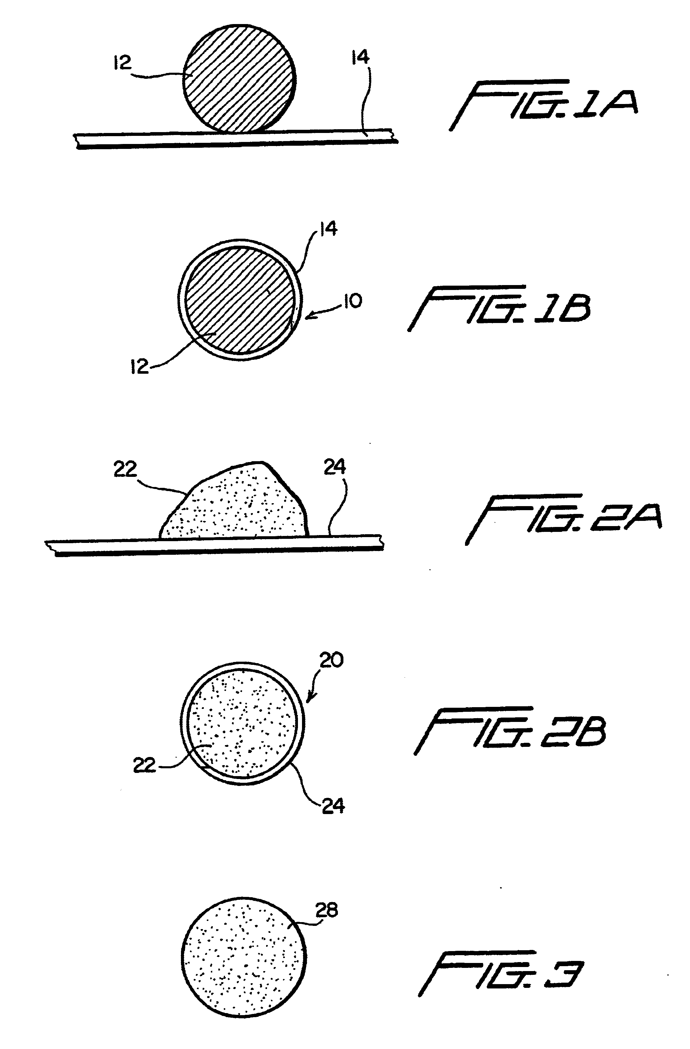
As shown in FIG. 1A, a solid wire 12 of copper, of copper alloy, or of a combination of copper and copper alloy is to be enclosed in an outer cladding or sheath 14 of aluminum, aluminum alloy, or a combination of the two. Any suitable known process for forming the resultant wire 10, FIG. 1B, may be used. In one aspect a known tube mill process is used to form a flat strip into a tube around a core, either powdered or solid.

In another aspect as shown in FIGS. 2A and 2B, an amount of powder 22 of copper, copper alloy, or both is used to form the core of a wire 20 that has an outer cladding or sheath 24 of aluminum, aluminum alloy, zinc, and / or zinc alloy. It is within the scope of this invention to feed core material powder and sheath material powder to a spray apparatus instead of feeding wire.

FIG. 3 shows a wire 28 according to the present invention which is formed by melting aluminum (and / or aluminum alloy), adding and melting copper (and / or copper alloy) to the aluminum melt, and ...


PUM

PropertyMeasurementUnit
thicknessaaaaaaaaaa
velocitiesaaaaaaaaaa
thicknessaaaaaaaaaa

Abstract

A method for applying wear reducing material to a tool joint useful in a wellbore in drilling operations, the method, in at least certain aspects, including positioning the tool joint adjacent laser beam apparatus, delivering wear-reducing material to a location on the tool joint to which the wear-reducing material is to be applied, heating the wear-reducing material with the laser beam apparatus to a temperature not exceeding its melting temperature so that the wear-reducing material is welded to the tool joint; in one particular aspect, using a defocused laser beam to achieve desired heating temperatures; and, in one aspect, defocusing the laser so no plasma is formed.

Description

BACKGROUND OF THE INVENTION1. Field of the InventionThe present invention is directed to improved tool joints used in wellbore operations; such tool joints that have wear-reducing material applied thereto, including, but not limited to hardfacings and carbides; and methods for applying such materials to tool joints.2. Description of Related Art“Thermal spraying” refers to a variety of processes for depositing both metallic and non-metallic materials on a substrate to form a coating. Metals, cermets, ceramics, plastics and mixtures thereof in the form of powders, rods or wires may be used as coating material. Heat for melting the material is supplied by electric arc, plasma arc, or combustible fuel gases and compressed air or process gases form an accelerated stream of molten coating material. The material builds up on the substrate and cools to form the coating.Electric arc spray processes use electrically charged wire which is fed by a wire feeder to an arc spray gun in which the w...

Claims


Application Information

Patent Timeline
Patent Type & Authority Patents(United States)
IPC IPC(8): C23C30/00C23C24/08C23C26/02C23C24/10C23C26/00C23C24/00
CPCC23C24/08C23C24/10C23C30/005C23C26/02C23C26/00
Inventor BOLTON, JIMMIE BROOKSROGERS, BILLI MARIE
Owner MCCLUNG GUY L III
Why Eureka
Try Eureka