Free-standing and aligned carbon nanotubes and synthesis thereof
a carbon nanotube and free-standing technology, applied in the field of products, can solve the problems of limited progress in the control of the placement of nanotubes, limited nanotube alignment, and difficult and laborious techniques
- Summary
- Abstract
- Description
- Claims
- Application Information
AI Technical Summary
Benefits of technology
Problems solved by technology
Method used
Image
Examples
example 1
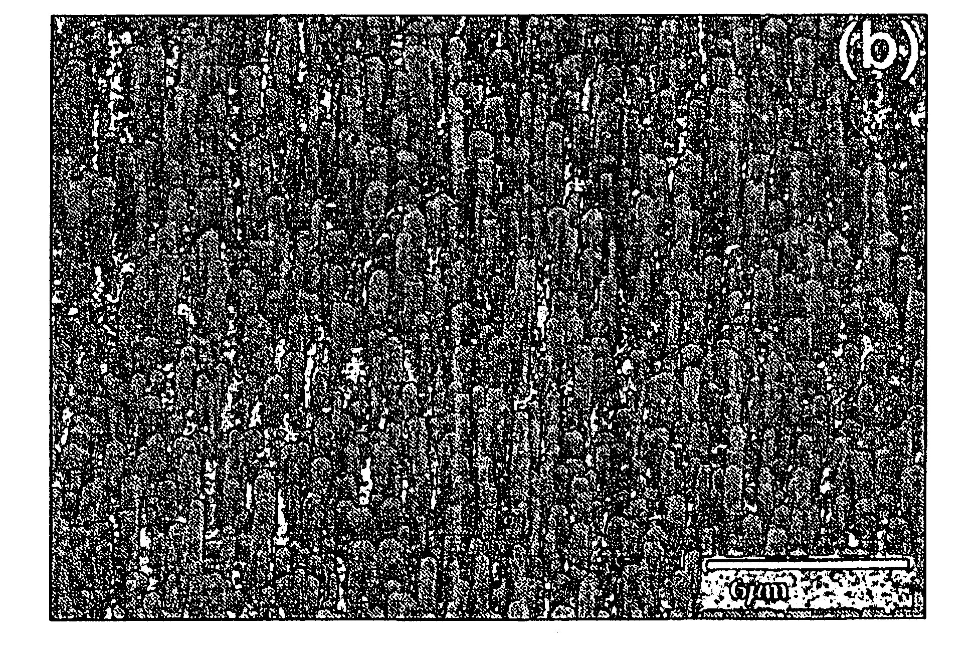
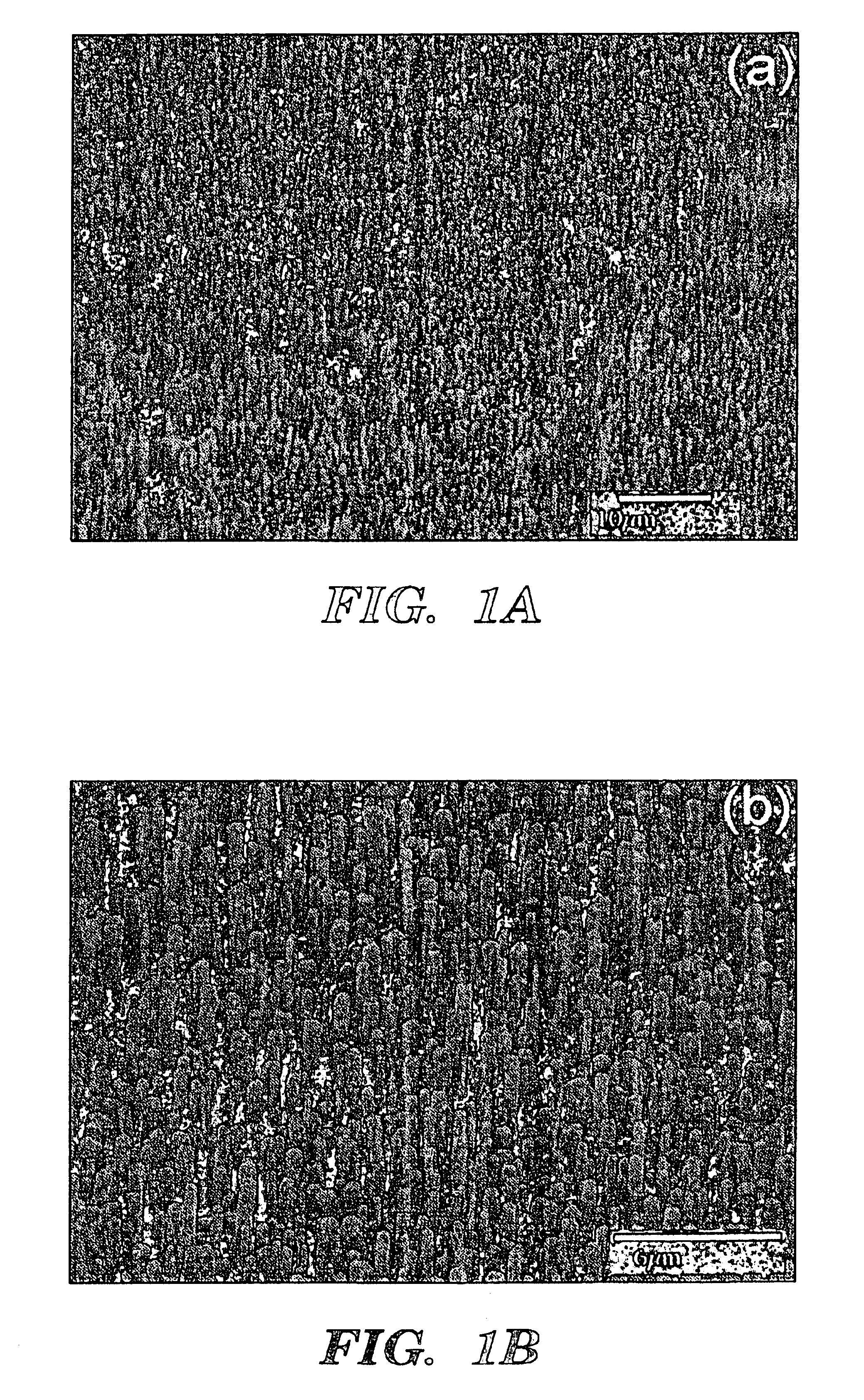
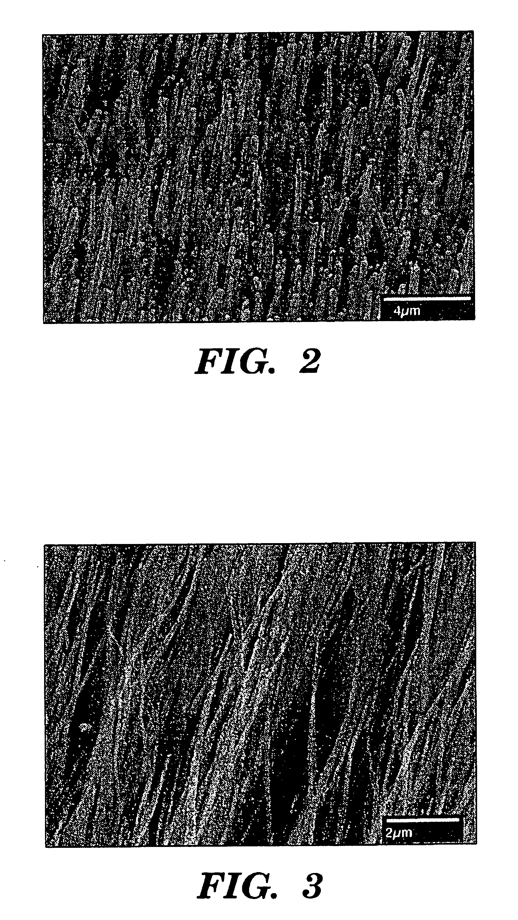
[0083]Polished polycrystalline and single-crystal Ni substrates were placed into a chemical vapor deposition (CVD) chamber, and the pressure was reduced to −6 Torr. Acetylene gas (99.99% purity) and ammonia gas (99.99% purity) were introduced into the chamber at a total flow rate of 120-200 standard cm3 per minute (sccm) and at a maintained working pressure of 1-20 Torr under the conditions listed in Table 1. After stabilizing the working pressure, a tungsten filament coil powered by a DC source (a 0-500 V DC, 3 A power supply, Advanced Energy MDX 1.5K-magnetron drive) and a plasma-generator were energized to generate heat and plasma at a temperature below 666° C. to induce carbon nanotube growth. Samples of the carbon nanotubes were examined by scanning electron microscopy (SEM, Hitachi S-4000) to measure tube lengths, diameters, site distributions, alignment, density and uniformity. High-resolution transmission electron microscopy (TEM) was used to determine the microstructure of ...
example 2
[0088]Substrate Preparation
[0089]Display glass having a strain point temperature of 666° C. was cut into 10×5 mm pieces and cleaned in acetone by ultra-sonication. The cleaned pieces were mounted onto the surface of a stainless steel resistive heater, and the whole assembly was placed into a magnetron sputtering chamber. The chamber was pumped down below 8×10⁻⁶ Torr before argon gas was introduced into the chamber to maintain a working pressure of 20-60 mTorr. A nickel catalyst layer of 15 to 60 nm in thickness was deposited onto the glass substrates by magnetron sputtering for about 1.5 to 6 minutes. During deposition, the substrates were either heated or kept at room temperature.
[0090]Catalyst layered substrates were placed to a CVD chamber, which was pumped down below 6×10⁻⁶ Torr. As soon as the chamber pressure reached 6×10⁻⁶ Torr, acetylene and ammonia gases were introduced into the chamber to maintain a working pressure of 1-20 Torr during carbon nanotube growth. The total flo...
example 3
[0100]A glass substrate was prepared as in Example 2 with a 10-40 nm thick nickel catalyst layer having an as-sputtered smooth surface, as shown in FIG. 6C. Carbon nanotubes were grown by PE-HF-CVD for about 10 minutes as in Examples 1 and 2, except the acetylene and ammonia volume ratio was 1:2 to 1:4. FIG. 10 shows a large area growth of substantially vertically aligned carbon nanotubes. The length of the carbon nanotubes is up to 50 μm. The diameters are estimated to be in the range of 100-150 nm (See FIG. 14).
PUM
| Property | Measurement | Unit |
|---|---|---|
| Temperature | aaaaa | aaaaa |
| Temperature | aaaaa | aaaaa |
| Temperature | aaaaa | aaaaa |
Abstract
Description
Claims
Application Information
 - R&D
- Intellectual Property
- Life Sciences
- Materials
- Tech Scout
- Unparalleled Data Quality
- Higher Quality Content
- 60% Fewer Hallucinations
Browse by: Latest US Patents, China's latest patents, Technical Efficacy Thesaurus, Application Domain, Technology Topic, Popular Technical Reports.
© 2025 PatSnap. All rights reserved.Legal|Privacy policy|Modern Slavery Act Transparency Statement|Sitemap|About US| Contact US: help@patsnap.com


