Furthermore, the SMP architecture has the following advantages:1. The SMP architecture reduces cost over a redundant architecture by eliminating expensive redundant components because they are not necessary in order to provide single-
fault tolerance.2. The SMP architecture uses a parallel
multiprocessor architecture for
improved performance while retaining a “single processor-
programming” model thereby significantly reducing the complexity of a
software application when compared to a redundant architecture.3. The SMP architecture increases performance over a single processor controller since both processors can share the
processing work-load. For example, the processors can share the work-load by evenly balancing processor loading.
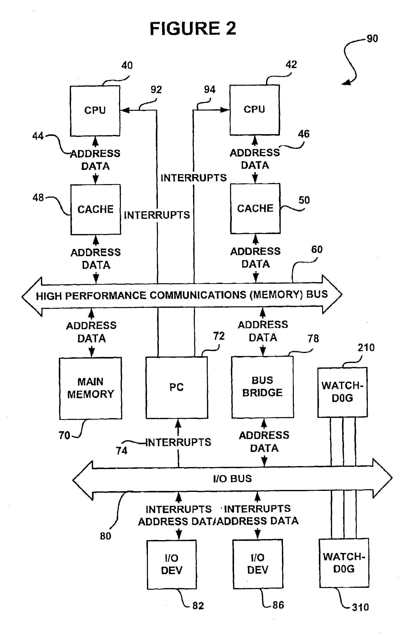
An SMP controller may use a single main memory shared by both CPUs in order to facilitate communication between the processors. As a result, cost is reduced by eliminating the expense of redundant components such as redundant processors, memory and memory busses. In one embodiment, the parallel processors in an SMP controller may use a common CPU
bus coupled to the
shared memory, or each processor may have their own CPU
bus coupled to a cache that is then linked with other processors through a separate
memory bus. In contrast, redundant designs require separate redundant memories in order to maintain true redundancy resulting in additional cost. In further contrast, the two, or in general n SMP processors provide the
advantage of high
throughput without the added cost of redundant memory.
Additionally, the SMP controller provides increased processor
throughput when compared with single processor controllers by operating on N processes in parallel without requiring redundant memory and without having a
single point of failure in the controller or computer. Therefore, the SMP controller uniquely combines the advantages of increased throughput provided by redundant processor controllers while maintaining the reduced cost advantages of a single processor controller.
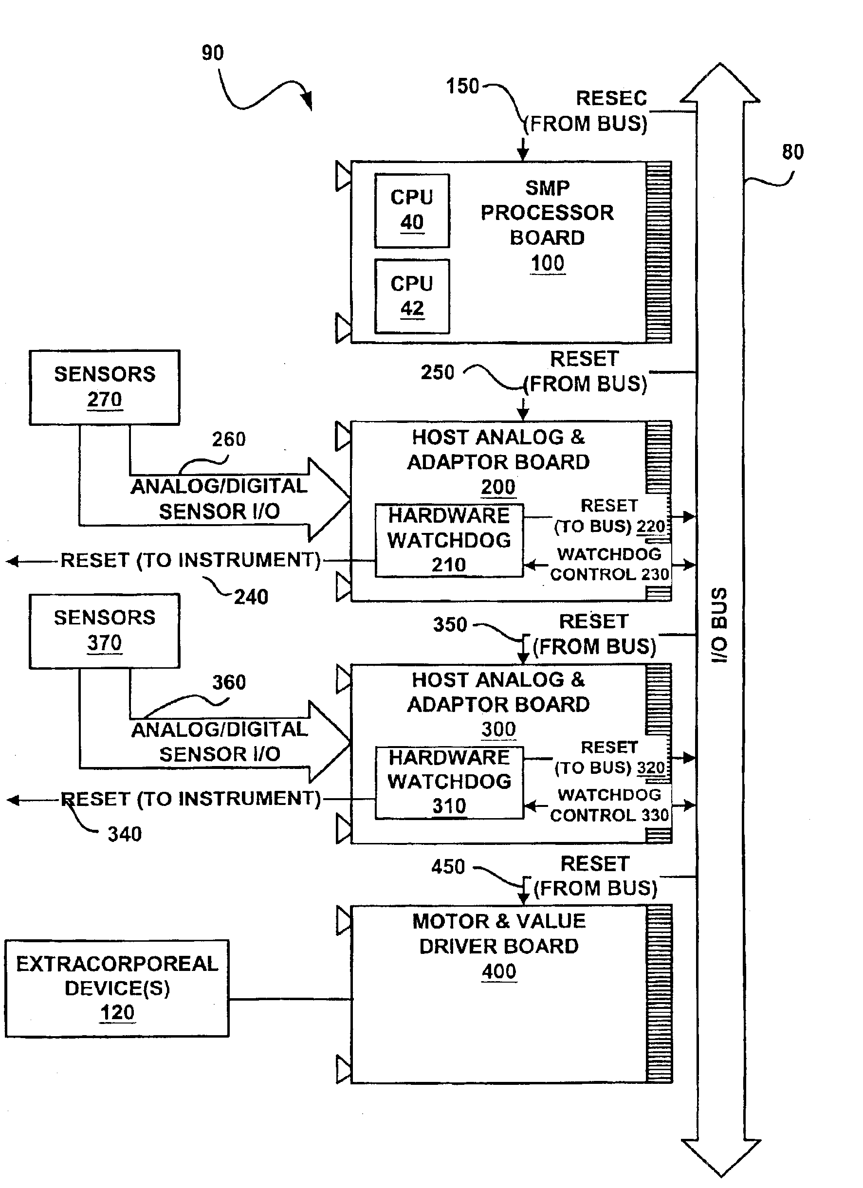
The SMP architecture may also connect to
host adapter boards for
interfacing with various dialysis machine and
extracorporeal circuits. For example, these devices may include active and passive components such as control devices, sensors, motors, heaters, pumps and valve drivers. The extracorporeal circuit devices, for example, may control the flow of blood in the dialysis machine. Further, the SMP architecture may be conveniently implemented into a modular computer
chassis of an SMP
processing board. Maintenance costs may be reduced as a result because a single board may be replaced more economically than replacing the entire controller.
A safety consideration with SMP architecture is that the
processor board itself, wherein the N tightly coupled processors may reside, may be
single fault tolerant by using a watch dog
timer circuit. Since there are no longer two fully independent redundant processors in the SMP architecture, such as those described in the Kenley et al. '851 patent cited above, a Byzantine failure on the
processor board (a bus lockup condition for example) may be rectified with a
watchdog timer resetting the processors. This prevents
software execution from stopping when the CPU or I / O bus locks up.
The
watchdog timer circuits may respond to a controller failure by delivering a
control signal to these various dialysis machine and extracorporeal circuits. As a result, the watchdog reset
signal may also be sent to the various hardware components such as the extracorporeal circuits of the dialysis machine in order to place the
system in a safe mode. Accordingly, the
control signal may effectively de-energize the extracorporeal control and hydraulics devices to cause the dialysis machine to assume the safe patient mode. The safe mode may also shut off the flow of blood to the patient from the dialysis machine in order to prevent any damaged or unsafe blood from flowing to the patient. For example, the flow of blood to the patient may be stopped by disabling the
blood pump and closing a clamp in the
venous line. A failure of the controller therefore effectively results in the dialysis machine entering the safe patient mode.

