
Physical vapor deposition apparatus and process

Inactive Publication Date: 2005-03-22
GENERAL ELECTRIC CO
View PDF9 Cites 14 Cited by
  • Summary
  • Abstract
  • Description
  • Claims
  • Application Information

AI Technical Summary

Benefits of technology

The PVD apparatus and process of this invention entail providing at lest two passages through which at lest two materials are fed into a coating chamber, and means for melting each of the materials to form molten pools thereof. A first of the materials has a composition with a higher vapor pressure than a second of the materials, and the melting means is operable to melt and evaporate the first and second ma

Problems solved by technology

Components within the turbine, combustor and augmentor sections of gas turbine engines are susceptible to oxidation and hot corrosion attack, in addition to high temperatures that can decrease their mechanical properties.
However, difficulties have been encountered when attempting to deposit beta-NiAl coatings alloyed with zirconium, hafnium, yttrium, cerium and / or another reactive element, as required by the NiAl compositions of Nagaraj et al., Darolia et al., Rigney et al., and Darolia.
For example, when attempting to evaporate an ingot of NiAl+Zr or NiAl+Cr+Zr, deposition rates are low and the chemistry of the coating has been difficult to control.

Method used


Image

  • Physical vapor deposition apparatus and process
  • Physical vapor deposition apparatus and process
  • Physical vapor deposition apparatus and process

Examples


Embodiment Construction

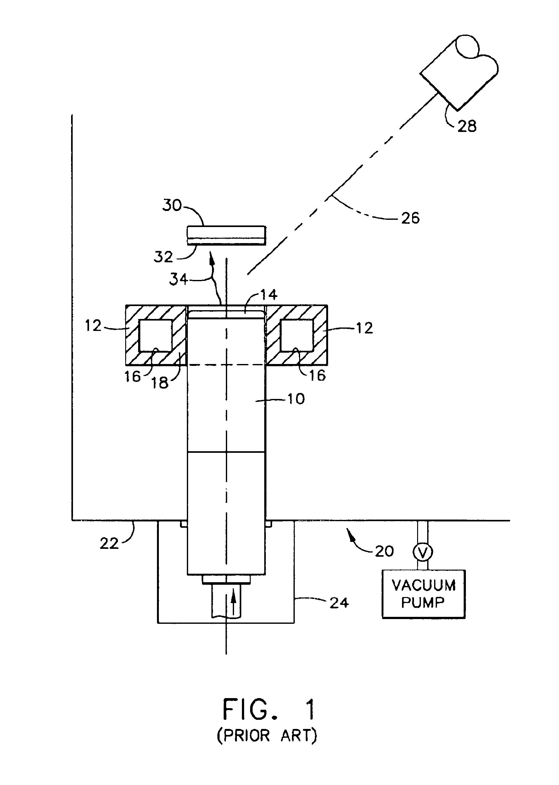
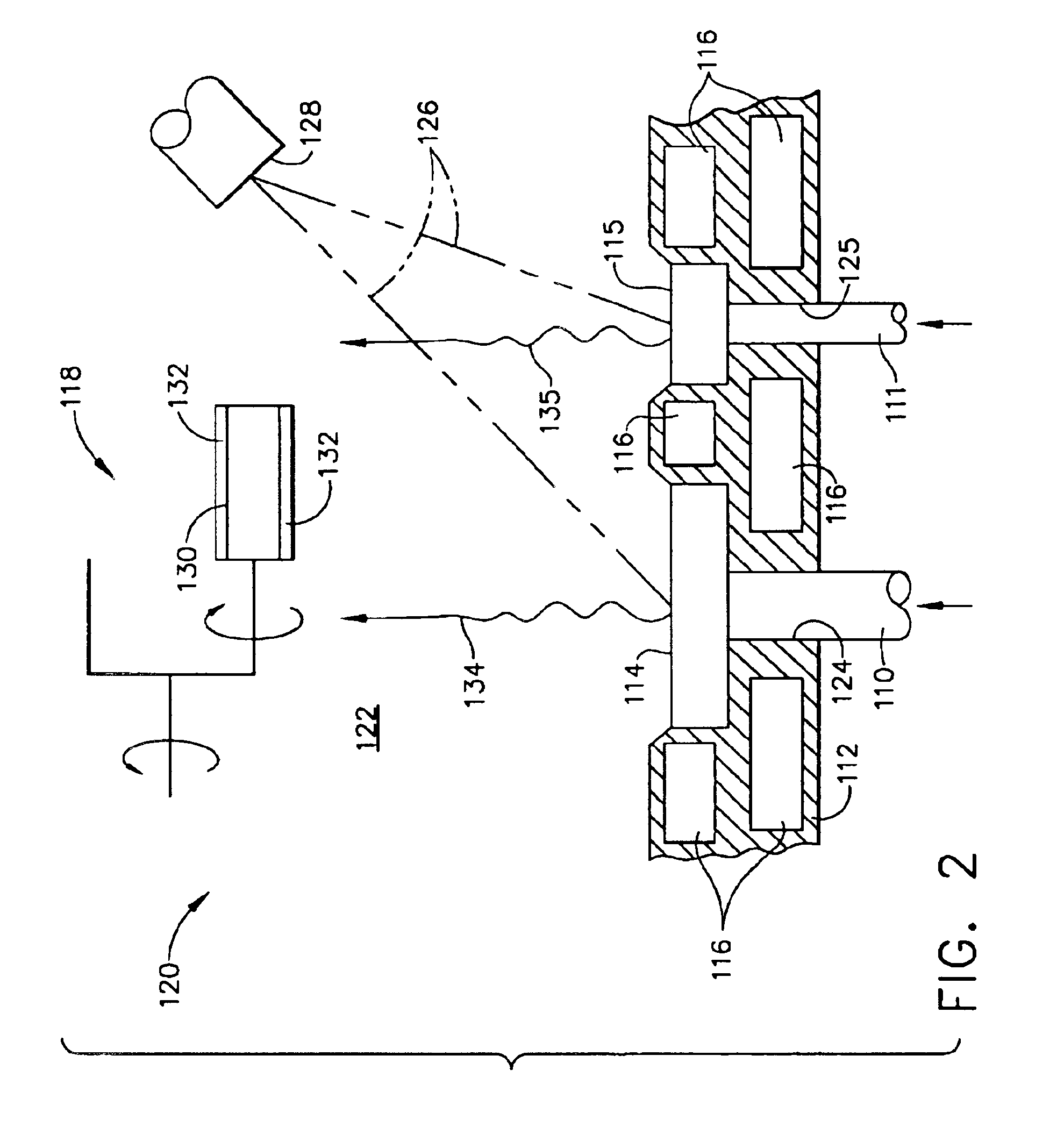
Three embodiments of a coating apparatus 120 are shown in FIGS. 2, 3 and 4 as being similar to the apparatus 20 of FIG. 1, and representative of a type suitable for depositing nickel-base intermetallic coatings. A particularly preferred coating material that can be deposited with the coating apparatus 120 is a beta-phase nickel aluminide, though it is also foreseeable that gamma-phase nickel intermetallics could be deposited.

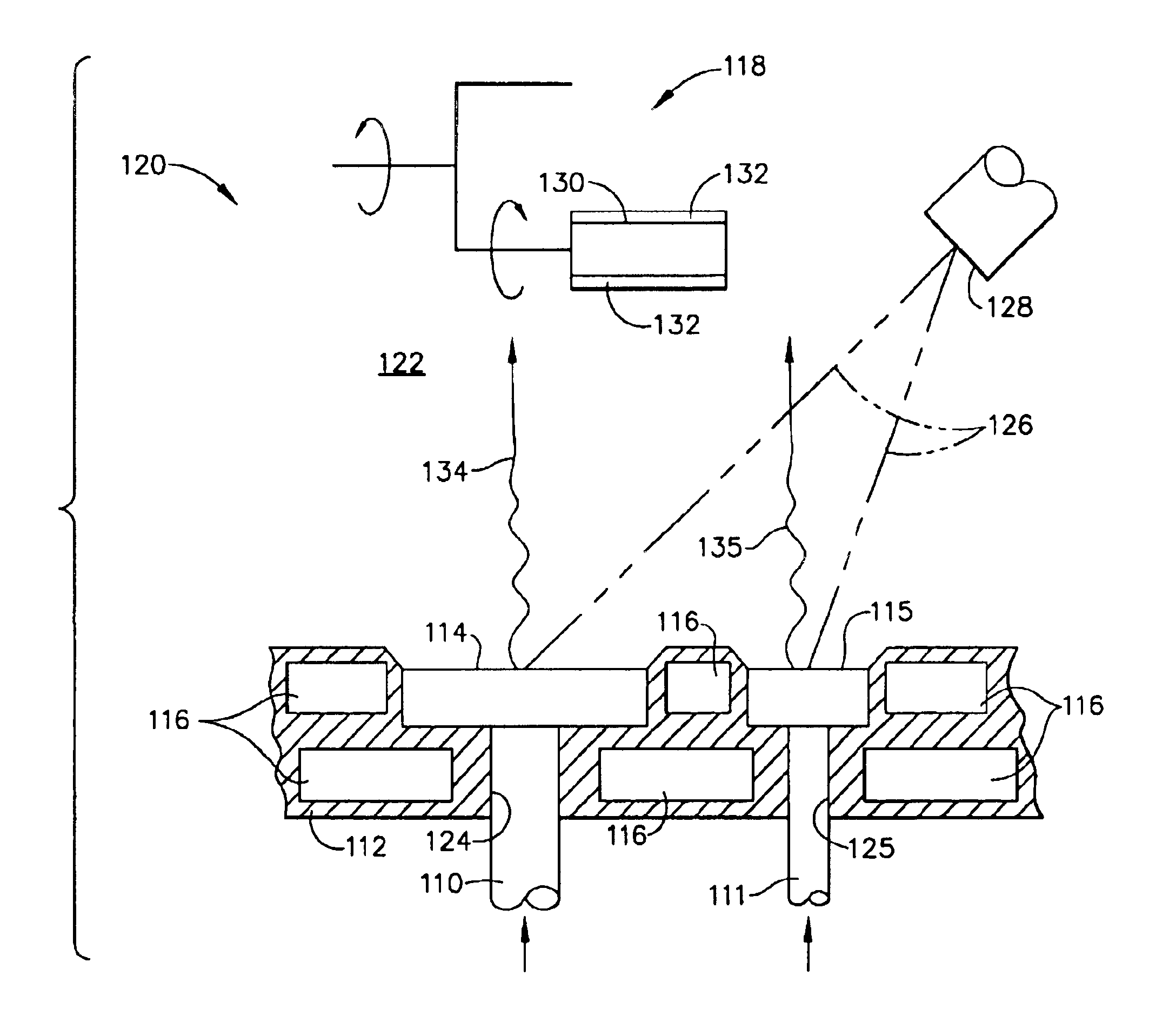
In FIG. 2, the apparatus 120 is shown as comprising a crucible 112 through which a pair of ingots 110 and 111 are fed into a coating chamber 122, and an electron beam (EB) gun 128 generates an electron beam 126 that, in combination with a controlled beam jumping technique, melts the upper surfaces of both ingots 110 and 111 to produce separate molten pools 114 and 115 of the ingot materials within the crucible 112. With such a technique, the beam 126 is briefly projected (in the millisecond range) on each ingot 110 and 111, with the amount of time on each ingot ...


PUM

PropertyMeasurementUnit
Vapor pressureaaaaaaaaaa

Abstract

A PVD process and apparatus (120) for depositing a coating (132) from multiple sources (110, 111) of different materials. The process and apparatus (120) are particulaity intended to deposit a beta-nickel aluminide coating (132) containing one or more elements whose vapor pressures are lower than NiAl. The PVD process and apparatus (120) entail feeding at least two materials (110, 111) into a coating chamber (122) and evaporating the materials (110, 111) at different rates from separate molten pools (114, 115) thereof. Articles (130) to be coated are suspended within the coating chamber (122), and transported with a support apparatus (118) relative to the two molten pools (114, 115) so as to deposit a coating (132) with a controlled composition that is a mixture of the first and second materials (110, 111).

Description

BACKGROUND OF INVENTION1. Field of the InventionThe present invention generally relates to coating apparatuses of the type used to deposit ceramic and metallic coatings. More particularly, this invention relates to a physical vapor deposition (PVD) apparatus and process for depositing a coating whose composition contains elements with relatively low and relatively high vapor pressures, such as a nickel aluminide alloyed with zirconium, hafnium, yttrium and / or cerium.2. Description of the Related ArtComponents within the turbine, combustor and augmentor sections of gas turbine engines are susceptible to oxidation and hot corrosion attack, in addition to high temperatures that can decrease their mechanical properties. Consequently, these components are often protected by an environmental coating alone or in combination with an outer thermal barrier coating (TBC), which in the latter case is termed a TBC system.Diffusion coatings, such as diffusion aluminides and particularly platinum ...

Claims


Application Information

Patent Timeline
IPC IPC(8): C23C14/16C23C14/28C23C14/30C23C14/24
CPCB82Y10/00C23C14/30C23C14/246C23C14/16
Inventor DAROLIA, RAMGOPALCORDERMAN, REED ROEDERRIGNEY, JOSEPH DAVIDNARDI, JR., RICHARD ARTHURWEIMER, MICHAEL JAMES
Owner GENERAL ELECTRIC CO
Learn More