
Electrolytic capacitor and a fabrication method therefor

a technology of electrolytic capacitors and fabrication methods, which is applied in the direction of electrolytic capacitors, capacitor dielectric layers, semiconductor/solid-state device details, etc., can solve the problems of reducing the leakage current in the electrolytic capacitor, obviating the decrease of electrical insulation, etc., and achieves the effect of less leakage curren

Inactive Publication Date: 2005-04-05
SANYO ELECTRIC CO LTD
View PDF9 Cites 52 Cited by
  • Summary
  • Abstract
  • Description
  • Claims
  • Application Information

AI Technical Summary

Benefits of technology

It is an object of the present invention to provide an electrolytic capacitor comprising an electrode with a dielectric layer formed by anodizing the electrode on a surface thereof, the capacitor with less leakage current obviating the decrease of electrical insulation by controlling crystallization of the dielectric layer in anodizing the electrode.
In the embodiment, the kind of niobium alloy is not limited, but it is preferable to use niobium alloy formed by alloying niobium with at least one type of additive metal selected from a group consisting of tungsten, vanadium, zinc, aluminum, molybdenum, hafnium, and zirconium, in order to control crystallization of the dielectric layer appropriately in anodizing the electrode. More preferably, when the electrode employing niobium alloy formed by alloying niobium with aluminum is anodized to form a dielectric layer, aluminum oxide as well as niobium oxide is contained in the dielectric layer. The excellent electrical insulation of aluminum oxide helps control crystallization of the dielectric layer in anodizing the electrode and leakage current.
When the fluorine-doped electrode of niobium or niobium alloy is anodized as suggested by the third electrolytic capacitor of the invention, the doped fluorine controls crystallization of the dielectric layer in anodizing the electrode and obviates decrease of electrical insulation to provide the capacitor with less leakage current.
Further, in the third electrolytic capacitor of the invention, the electrode employing niobium alloy is effective in controlling crystallization of the dielectric layer in anodizing the electrode. As for niobium alloy, it is preferred to use the niobium alloy formed by alloying niobium with aforesaid additive metal. It is also preferred that the additive metal content of the niobium alloy is in the aforesaid range.

Problems solved by technology

Consequently, the decrease of electrical insulation is obviated and leakage current in the electrolytic capacitor decreases.

Method used

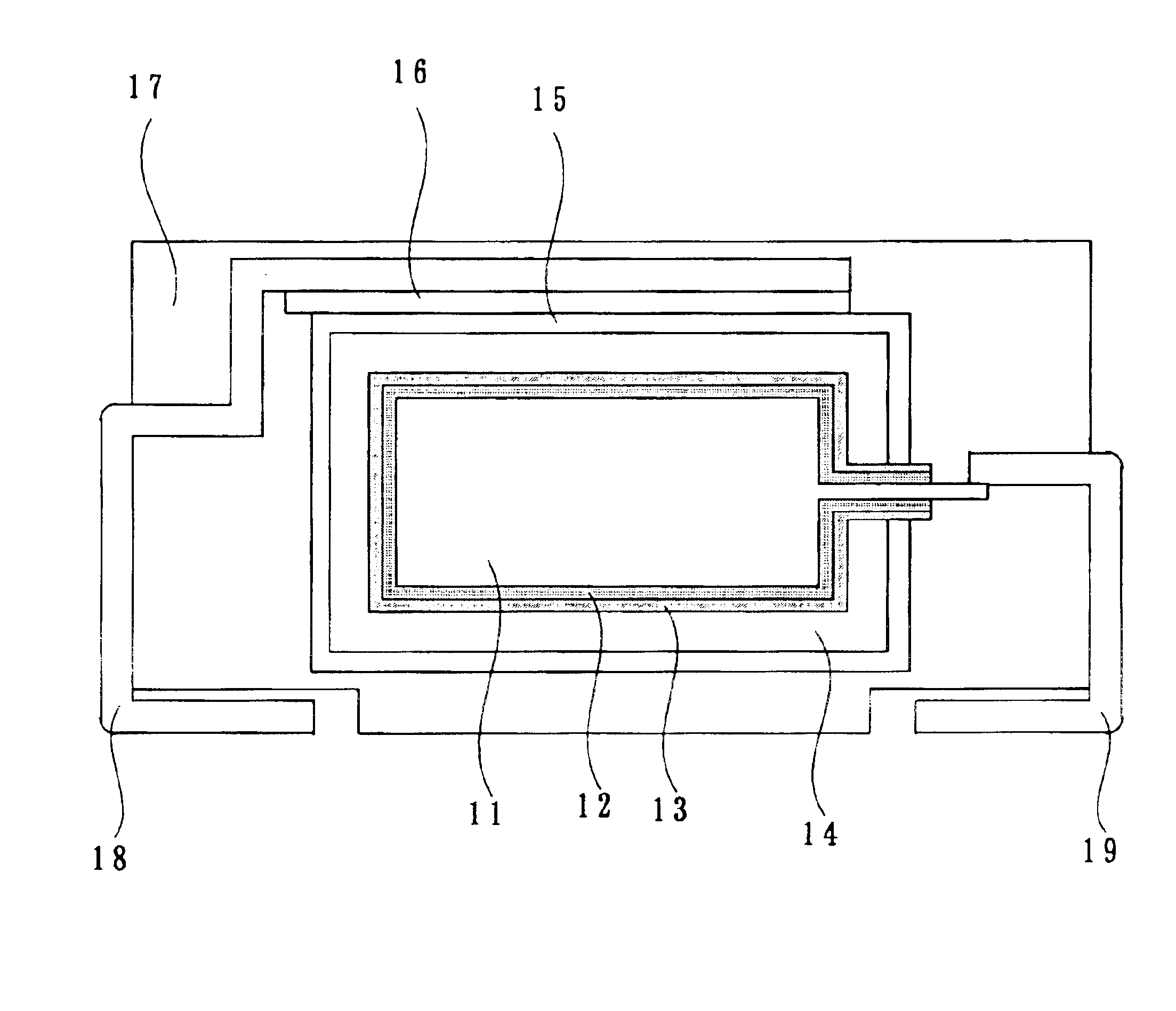
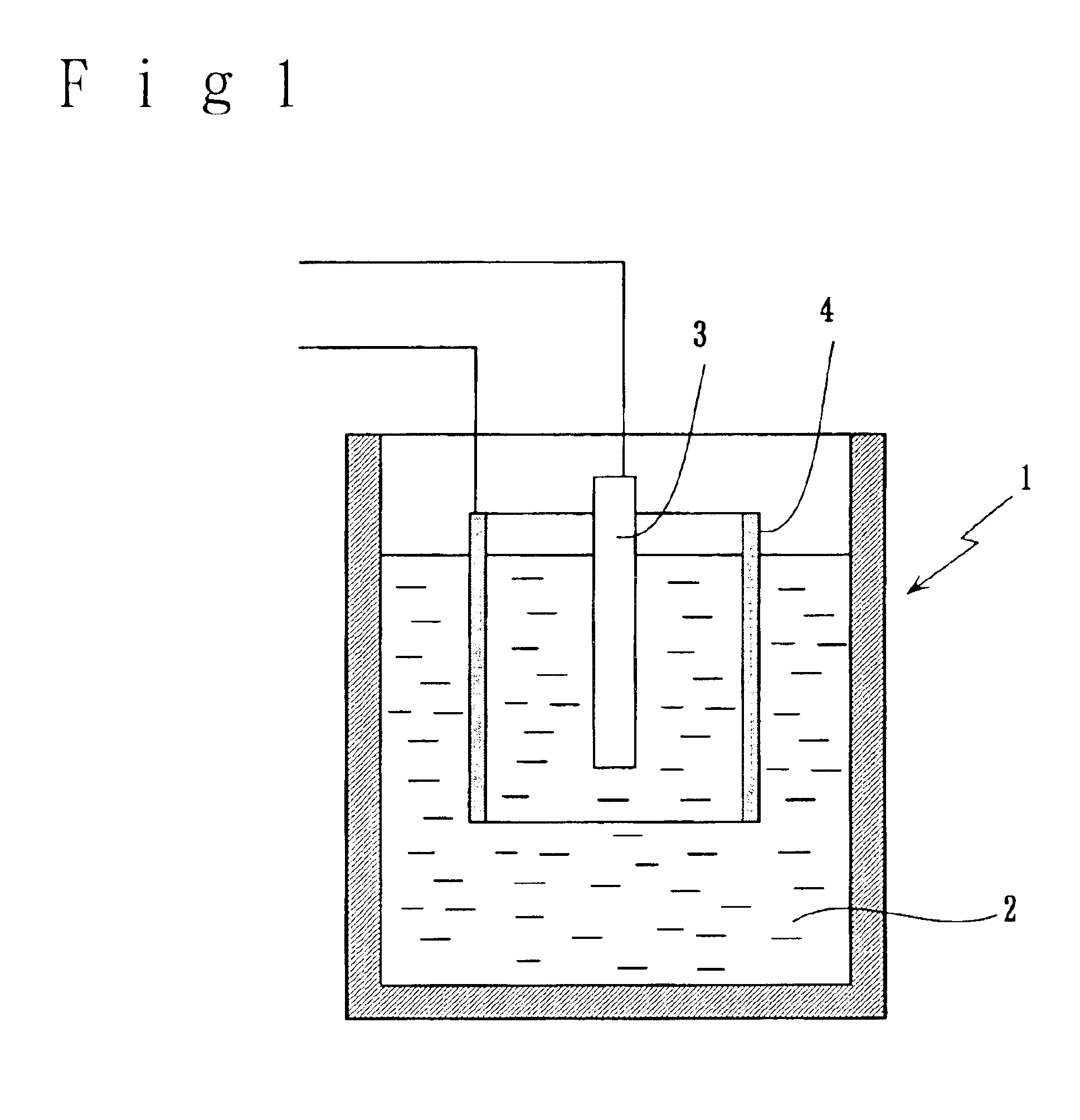
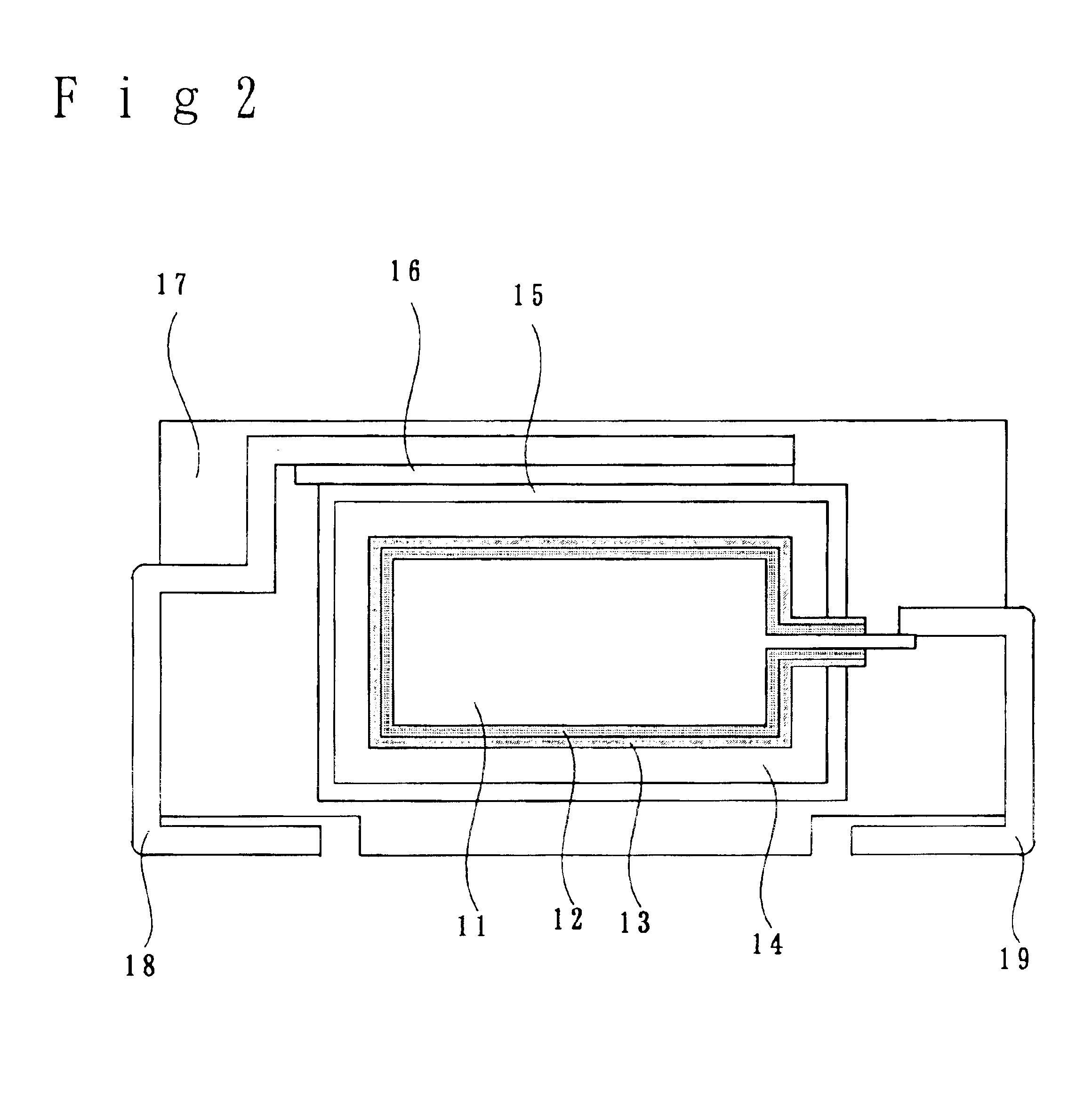

Image

  • Electrolytic capacitor and a fabrication method therefor
  • Electrolytic capacitor and a fabrication method therefor
  • Electrolytic capacitor and a fabrication method therefor

Examples


example a2

The same procedure as in Example A1 was used to fabricate a trial electrolytic capacitor of Example A2, except for the kind of additive metal. 1 g of vanadium(V) powder in place of tungsten powder in Example A1 was added to 99 g of niobium powder.

example a3

The same procedure as in Example A1 was used to fabricate a trial electrolytic capacitor of Example A3 except for the kind of additive metal. 1 g of Zinc(Zn) powder in place of tungsten powder in Example A1 was added to 99 g of niobium powder.

example a4

The same procedure as in Example A1 was used to fabricate a trial electrolytic capacitor of Example A4 except for the kind of additive metal. 1 g of aluminum(Al) powder in place of tungsten powder in Example A1 was added to 99 g of niobium powder.


PUM

PropertyMeasurementUnit
boiling pointaaaaaaaaaa
thicknessaaaaaaaaaa

Abstract

An electrolytic capacitor including one type of electrode selected from a group consisting of an electrode of at least one type of alloy selected from a group consisting of niobium alloy, titanium alloy, and tungsten alloy, an electrode of mixed sinter of niobium and aluminum, or a fluorine-doped electrode of niobium or niobium alloy and on a surface of each electrode a dielectric layer is formed by anodizing the electrode.

Description

BACKGROUND OF THE INVENTION1. Field of the InventionThe present invention relates to an electrolytic capacitor and a fabrication method therefor, the electrolytic capacitor forming a dielectric layer by anodizing an electrode on a surface thereof. More particularly, the invention relates to an electrolytic capacitor featuring control of decrease of electrical insulation caused by crystallization of the dielectric layer in anodizing the electrode, and decreasing leakage current in an electrolytic capacitor.2. Description of the Related ArtRecently, miniaturization of electronic machines has been bringing about a demand for a small-sized capacitor of great capacitance.Capacitors having high capacitance are proposed as disclosed in JP-A-5-121275, such as an electrolytic capacitor employing titanium as an electrode and forming a dielectric layer of titanium oxide by anodizing the electrode, or as disclosed in JP-A-11-312628, which discloses an electrolytic capacitor forming a dielectric...

Claims


Application Information

Patent Timeline
Patent Type & Authority Patents(United States)
IPC IPC(8): H01G9/00H01G9/04H01G9/004H01G9/042H01G9/07H01L29/76H01L23/52H01L29/66H01L23/48H01L29/40H01G9/052H01G9/15
CPCH01G9/042H01G9/15H01G9/052
Inventor YANO, MUTSUMITAKATANI, KAZUHIROKIMOTO, MAMORU
Owner SANYO ELECTRIC CO LTD
Learn More