Catalyst and process for exhaust purification

a technology of catalyst and exhaust, applied in the direction of metal/metal-oxide/metal-hydroxide catalyst, machine/engine, arsenic compound, etc., can solve the problem of torque shock upon inserting a rich spike, the difficulty of continuously providing hc and co in an amount for sufficiently reducing no/sub>x,

Inactive Publication Date: 2005-04-12
MITSUBISHI ELECTRIC CORP
View PDF3 Cites 42 Cited by
  • Summary
  • Abstract
  • Description
  • Claims
  • Application Information

AI Technical Summary

Benefits of technology

The present invention relates to an electrochemical catalyst for exhaust purification comprising a catalyst A containing an NOx absorbing substance and an NOx reducing catalyst, a catalyst B containing a hydrocarbon adsorption substance and a hydrocarbon lo oxidizing catalyst, an electron conductive substance C, and an ion conductive substance D.

Problems solved by technology

However, methods for burning fuel under a lean condition such as a lean-burn engine and GDI (gas direct injection) engine are used in order to improve efficiency of a combustion engine, making it difficult to constantly supply HC and CO in an amount for sufficiently reducing NOx.
However, since the NOx absorbing substance deteriorates due to sulfur poisoning and NOx absorbing capability is changed, it is difficult to predetermine timing for providing the rich driving mode and timing for a reactivation process for the sulfur poisoning.
Moreover, there arises a problem such as torque shock upon inserting a rich spike, depending on driving modes.
However, since an oxidation reaction and a reduction reaction are independent chemical reactions, the effect of accelerating the oxidation reaction and the reduction reaction is small, and it is necessary that the reducing reagent and the oxidizing reagent exist in a sufficient amount in a gaseous phase.
However, this system has been invented as a combustion exhaust processing method for a power plant, and it can not be applied to an automobile from the viewpoint of volume, weight, control, costs and the like.
However, these systems have also been devised as a combustion exhaust processing method for a power plant, and have not been applied to an automobile from the viewpoint of volume, weight, control, costs, and the like.

Method used


Image

  • Catalyst and process for exhaust purification
  • Catalyst and process for exhaust purification
  • Catalyst and process for exhaust purification

Examples


embodiment 1

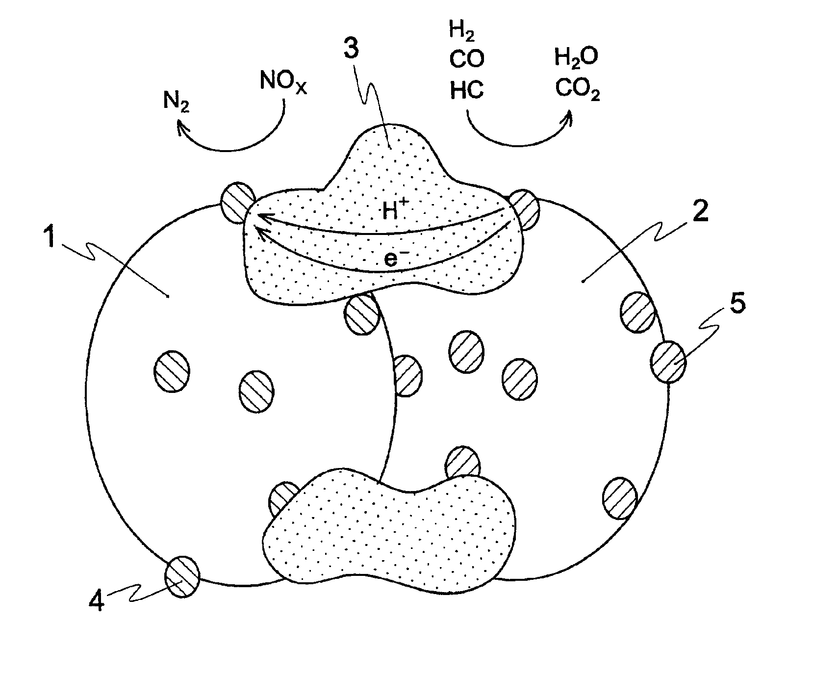
FIG. 1 is a schematic view that shows a catalyst for exhaust purification in Embodiment 1. In the FIG., 1 represents a catalyst A containing an NOx absorbing substance and an NOx reducing catalyst, 2 represents a catalyst B containing a hydrocarbon (HC) adsorption substance and an HC oxidizing catalyst, 4 represents a particle of noble metal reducing catalyst, 5 represents a particle of noble metal oxidizing catalyst, 6 represents an ion conductive solid electrolyte, and 7 represents a metal honeycomb. Solid-line arrows in the solid electrolyte 6 indicate flow of electrons (e−) and flow of ions (protons: H+). In Embodiment 1, the solid electrolyte 6 deals with only ion conduction and the metal honeycomb 7 deals with electron conduction.

Since the metal honeycomb 7 can maintain a sufficient strength even if it is thinner than a ceramics honeycomb, pressure loss thereof becomes low. Moreover, since it also has advantages such as excellent heat conduction, it is coated with a catalyst f...

embodiment 2

FIG. 3 is a schematic view that shows an electrochemical catalyst for exhaust purification in Embodiment 2.

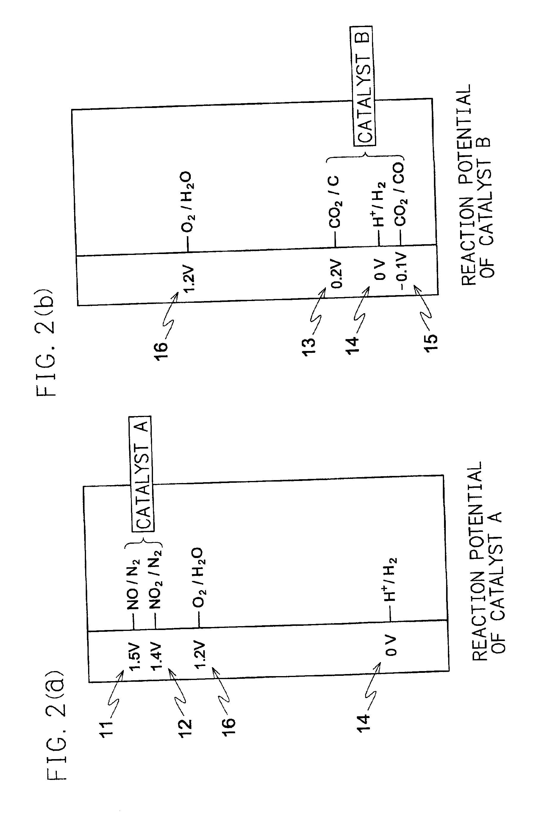
As the state of ion conduction, Embodiment 2 does not show the proton conduction, but the oxygen ion conduction. In case of the oxygen ion conduction, the reactions of the above-mentioned formulas (1) to (5) are respectively replaced by the reactions shown in the following formulas (6) to (10), but the reactants and the like are basically the same.

[Reducing Electric Potential]

2NO+4e−→N2+2O2−  (6)

2NO2+8e−→N2+4O2−  (7)

[Oxidizing Electric Potential]

C+2O2−→CO2+4e−  (8)

H2+O2−→H2O+2e−  (9)

CO+O2−→CO2+2e31   (10)

As the solid electrolyte 6 having ion conductivity, for example, there are perovskite ceramics disclosed in Japanese Unexamined Patent Publication NO. 8-332342 / 1996, and this can be used at an operation temperature and an atmosphere suitable for a catalyst for exhaust purification. Moreover, there may be used a solid electrolyte 6 having electron conductivity and ion conductivi...

embodiment 3

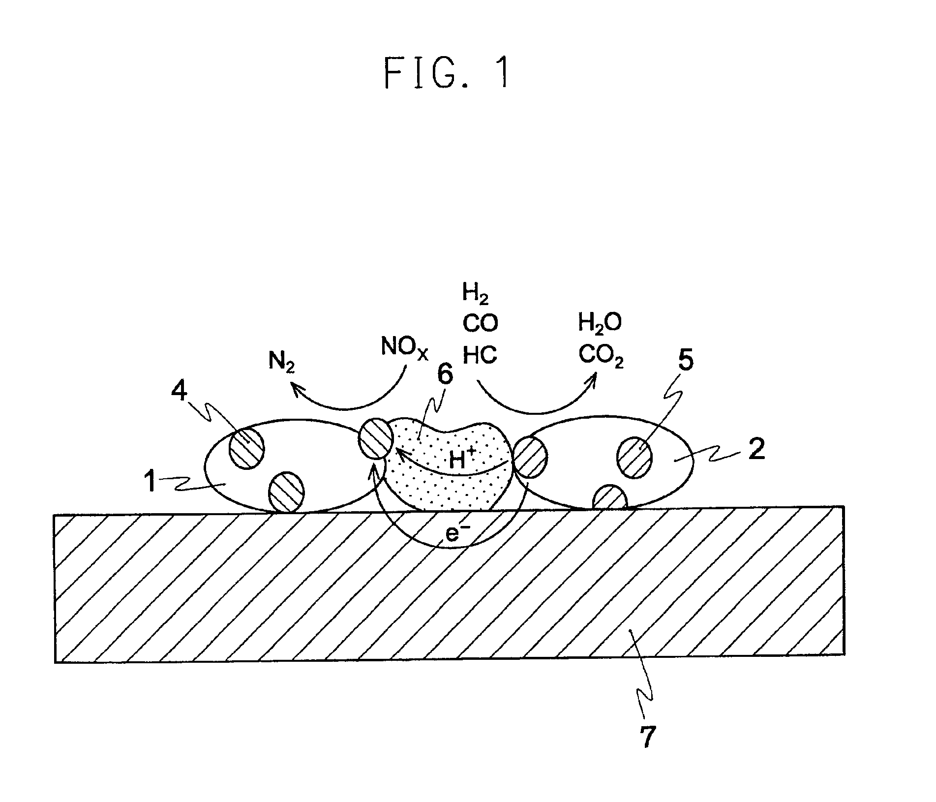
FIG. 4 is a schematic view that shows a catalyst for exhaust purification in Embodiment 3. In this Figure, 1 represents a catalyst A containing an NOx absorbing substance and an NOx reducing catalyst, 2 represents a catalyst B containing a hydrocarbon (HC) adsorption substance and an HC oxidizing catalyst, 3 is a mixture of an electron conductive material C and an ion conductive substance D (solid electrolyte), 4 represents particles of noble metal reducing catalyst, 5 represents particles of noble metal oxidizing catalyst. And solid-line arrows in the solid electrolyte 3 indicate flow of electrons and flow of ions (protons).

Concrete compositions, methods for preparation and evaluation results including Comparative Examples are shown in Examples. In the present Embodiment 3, the basic construction of the present invention wherein protons are used as ion conductor and the reasons for revealing effects are explained in detail by referring to FIGS. 4 and 2.

The mixture of the electron c...


PUM

PropertyMeasurementUnit
electromotive forceaaaaaaaaaa
electric potentialaaaaaaaaaa
electron conductiveaaaaaaaaaa

Abstract

A catalyst for internal combustion engine exhaust purification without frequently switching to a rich burn mode. The catalyst includes a catalyst A containing an NOx absorbing substance and an NOx reducing catalyst, a catalyst B containing a hydrogen adsorption substance and a hydrogen oxidizing catalyst, an electron conductive substance C, and an ion conductive substance D. Electrons move between the catalyst A and the catalyst B through the electron conductive substance C, ions move through the ion conductive substance D, and an electrochemical reducing reaction and an electrochemical oxidizing reaction respectively occur on the catalyst A and on the catalyst B. Therefore, it is possible to quickly reduce the adsorbed NOx using the adsorbed hydrogen without depending on the atmosphere.

Description

BACKGROUND OF THE INVENTIONThe present invention relates to a catalyst for exhaust purification, which can purify exhaust from a combustion engine such as a vehicle or a diesel car. And particularly it relates to an electrochemical catalyst for exhaust purification, which can store both NOx and hydrocarbons and electrochemically react NOx, with hydrocarbons.A conventional catalyst for exhaust purification, as typically a ternary catalyst, has played an important role in reducing an exhausted quantity of NOx, CO and HC by carrying out a reduction reaction reducing nitrogen oxides such as NO and N02 to nitrogen and an oxidation reaction oxidizing reductive substances such as hydrocarbons (HC) and CO on the same catalyst. However, methods for burning fuel under a lean condition such as a lean-burn engine and GDI (gas direct injection) engine are used in order to improve efficiency of a combustion engine, making it difficult to constantly supply HC and CO in an amount for sufficiently r...

Claims


Application Information

Patent Timeline
Patent Type & Authority Patents(United States)
IPC IPC(8): B01J23/63B01J23/656B01J23/54B01J23/00B01D53/94B01J23/10B01J23/89B01J35/00B01J37/00B01J37/02H01M8/00H01M8/12H01M8/06F01N3/08
CPCB01D53/9422B01J23/002B01J23/10B01J23/63B01J23/6562B01J23/8946B01J35/0033B01J37/0225B01J37/0246F01N3/0814F01N3/0835F01N3/0842H01M8/00Y02E60/525B01D2255/1025B01D2255/2025B01D2255/2027B01D2255/2042B01D2255/2063B01D2255/20753B01J2523/00H01M8/0662H01M2008/1293B01D2255/1021Y02E60/50B01J2523/36B01J2523/48B01J2523/24B01J2523/35B01J2523/3706B01J2523/72B01J2523/22B01J2523/32
Inventor MITSUDA, KENROSATOU, MINORUSIGEOKA, HIROAKINISHIYAMA, RYOJIKISHIMOTO, YUJIKATASHIBA, HIDEAKIOOUCHI, HIROFUMI
Owner MITSUBISHI ELECTRIC CORP
Why Eureka
Try Eureka