Quadrature amplitude modulation demodulator and receiver

a qam and receiver technology, applied in the field of qam demodulators, can solve the problems of inability to make adc sampling rate equal, inability to make timing synchronisers work normally, and inability to make timing errors, etc., to achieve rapid and reliable locking of an incoming qam signal, poor signal-to-noise ratio, and high multipath

Inactive Publication Date: 2005-04-12
INTEL CORP
View PDF7 Cites 10 Cited by
  • Summary
  • Abstract
  • Description
  • Claims
  • Application Information

AI Technical Summary

Benefits of technology

It is thus possible to provide a demodulator which is capable of rapidly and reliably locking onto an incoming QAM signal even when such a signal has a poor signal-to-noise ratio and high multipath. By initially using the highest sweep rate, false locking in the presence of good quality incoming signals can be substantially avoided or reduced. By reducing the sweep rate as necessary until lock is achieved, even poor quality signals can be captured with a high probability. Thus, compromises in sweep rate and demodulator synchronisation can be substantially avoided or reduced.

Problems solved by technology

It is not practical to make the ADC sampling rate equal to a multiple of the symbol rate because this may vary for any given communication channel.
When the re-sampling phase matches the timing used by the transmitting modulator, the timing error vanishes and the DPLL locks.
The incoming QAM signal may have a wide range of signal-to-noise ratios and an unpredictable amount of multipath.
If the sweep rate is chosen to be sufficiently low to permit locking in conditions where the incoming signal has a low signal-to-noise ratio and / or is subjected to a high level of multipath, the timing synchroniser may lock incorrectly when presented with a signal of higher signal-to-noise ratio and / or of lower multipath.
Conversely, if the sweep rate is relatively high, the timing synchroniser may fail to lock in the presence of signals of poorer signal-to-noise ratio and / or multipath.
Conversely, if a lower sweep rate is chosen, the presence of high quality incoming signals may result in false lock being achieved.

Method used


Image

  • Quadrature amplitude modulation demodulator and receiver
  • Quadrature amplitude modulation demodulator and receiver
  • Quadrature amplitude modulation demodulator and receiver

Examples


Embodiment Construction

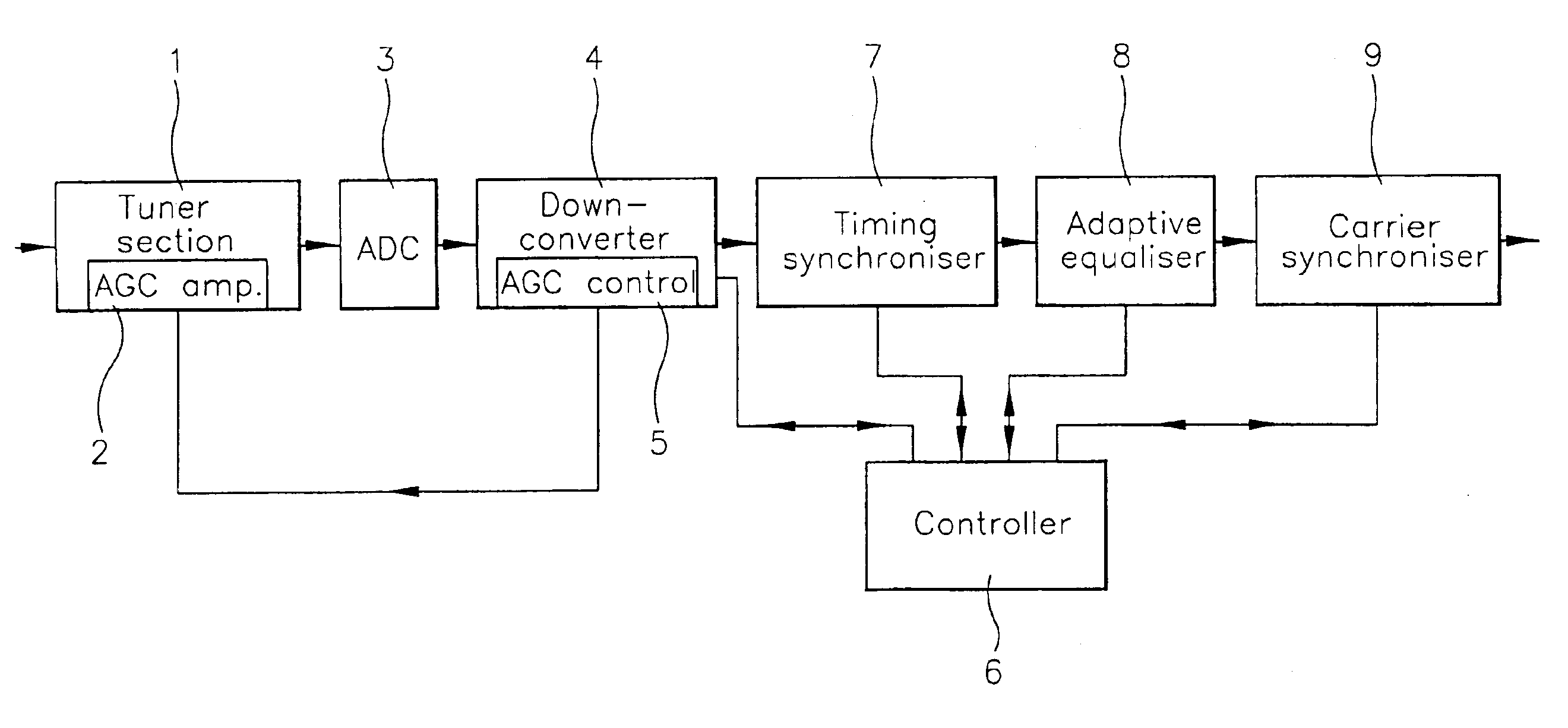
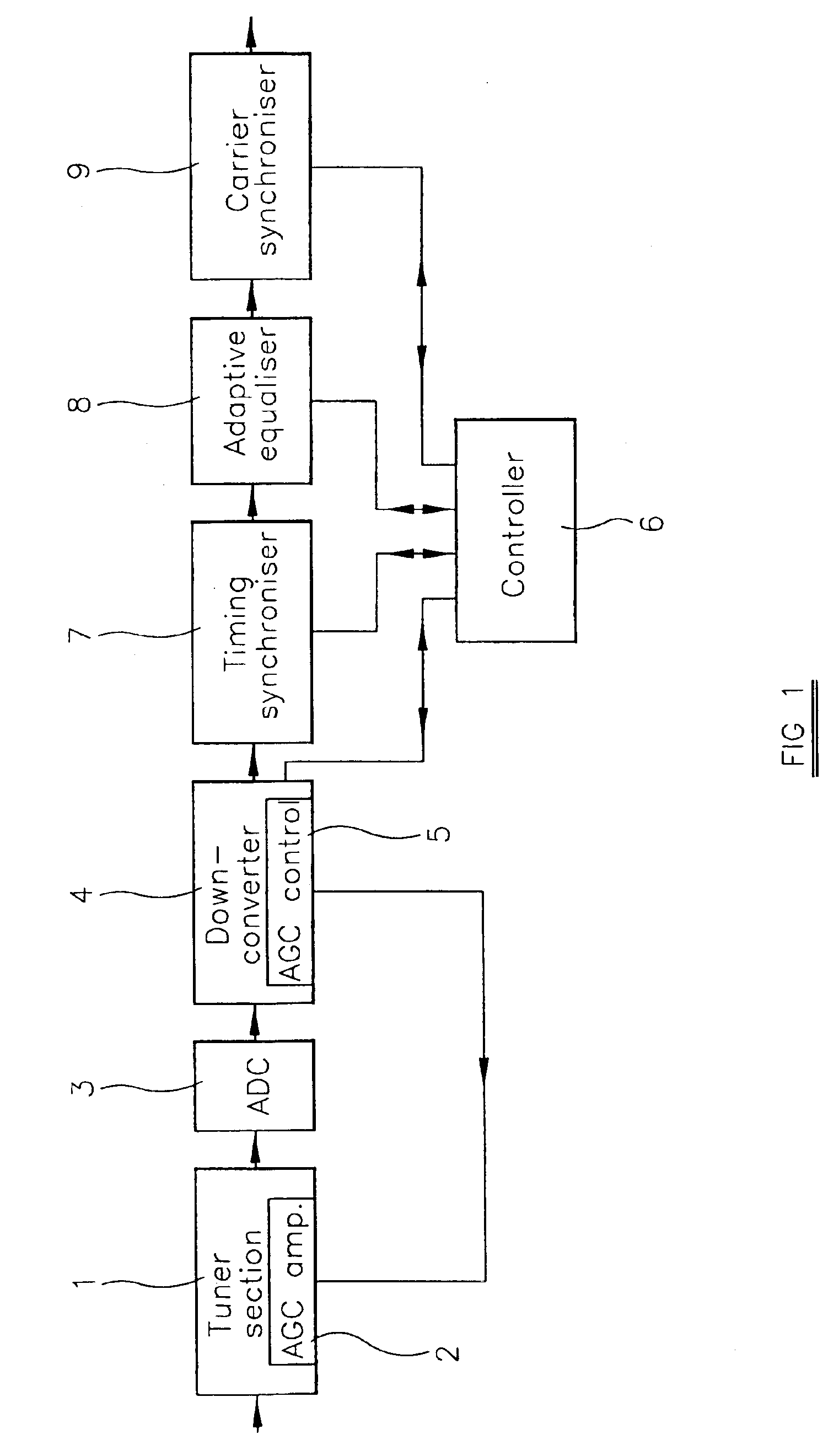
The tuner and demodulator shown in FIG. 1 comprise a tuner section 1 which receives a signal, for example, from a cable distribution network or a satellite aerial via a suitable head unit. As is known, the tuner section 1 selects a desired channel and converts this to a fixed intermediate frequency. The tuner section 1 also includes an automatic gain control (AGC) amplifier 2 whose gain is controlled so as to present signals of substantially constant amplitude envelope at the output of the tuner section 1.

In a typical example of such a tuner and demodulator for use with a cable network, the tuner section 1 selects a channel having a bandwidth of 6 or 8 MHz centred at 7 MHz. This signal is supplied to an analogue-to-digital converter (ADC) 3 which samples the incoming analogue signal and converts the samples to digital code. In practice, the ADC 3 is free-running in the sense that its sampling rate is not phase-locked to the transmitted symbol clock. It is not possible to make the sa...


PUM


Abstract

A QAM demodulator comprises a timing synchronizer whose output is supplied via an adaptive equalizer to a carrier synchronizer, all of which are controlled by a controller. The timing synchronizer resamples the incoming signal in the digital domain with a sampling period which, during an acquisition mode, sweeps between limit values at different rates. The controller begins an acquisition cycle at the highest rate and monotonically lowers the sweep rate until timing lock is achieved. The sampling rate is then fixed at the correct value. Similarly, the controller sweeps the local oscillator of a phase locked loop in the carrier synchronizer initially at a highest rate and at progressively lower rates until the carrier synchronizer locks to the phase of the incoming signal.

Description

BACKGROUND OF THE INVENTION1. Field of the InventionThe present invention relates to a quadrature amplitude modulation (QAM) demodulator, for example for demodulating digital video and data signals transmitted via cable or wireless channels, and to a receiver including such a demodulator.2. Description of the Prior ArtQAM is used for transferring digital video and data signals over cable or wireless channels. In this modulation scheme, the phase and amplitude of a sinusoidal carrier wave are modulated by the digital information. For example, in the modulation scheme known as QAM256, each symbol is chosen from a set of 256 possible amplitude-phase combinations. Thus, each symbol may represent 8 bits of digital data.Known types of QAM demodulators make use of timing synchronisers and carrier synchronisers. For example, a typical known timing synchroniser resamples incoming sampled digital signals from an upstream analogue-to-digital converter (ADC). The ADC is free-running in the sens...

Claims


Application Information

Patent Timeline
Patent Type & Authority Patents(United States)
IPC IPC(8): H04L7/02H04L27/38H04L27/227H04L7/10H04L27/00H04L25/03
CPCH04L7/0004H04L27/2272H04L27/3818H04L7/0029H04L2025/03745H04L2027/0077H04L2027/0036H04L2027/0038H04L2027/0067H04L2027/0073H04L2027/003
Inventor ARAMBEPOLA, BERNARD
Owner INTEL CORP
Why Eureka
Try Eureka