Structure inspection device

a technology of structure inspection and inspection device, which is applied in the direction of acceleration measurement using interia force, specific gravity measurement, instruments, etc., can solve the problems of limited inspection range, affecting practicability, and affecting the inspection effect of supersonic waves

Inactive Publication Date: 2005-04-19
MITSUBISHI ELECTRIC CORP +1
View PDF21 Cites 27 Cited by
  • Summary
  • Abstract
  • Description
  • Claims
  • Application Information

AI Technical Summary

Benefits of technology

[0011]The present invention is intended to obviate the problems as referred to above, and has for its object to provide a structure diagnosis apparatus and a structure diagnosis method which are capable of objectively evaluate the internal condition of a concrete structure irrespective of surrounding noise or the shape of

Problems solved by technology

Moreover, attempts have been made to apply a destructive inspection using supersonic waves, but the frequency band efficiently output by known probes is several hundred kHz or more, so the supersonic waves are liable to be scattered by aggregates in the interior of the concrete structure because of their wave length, and the range capable of being inspected has been limited to a shallow area from the surface.
As a consequence, a certain period of time is required for preparation of the measurement, thus giving rise to a problem for practicable workability.
With such a conventional method, however, a resonance sound determined by the material and the shape of the hammer is generated from the hammer itself by an external impact and mixed with the stri

Method used


Image

  • Structure inspection device
  • Structure inspection device
  • Structure inspection device

Examples


embodiment 1

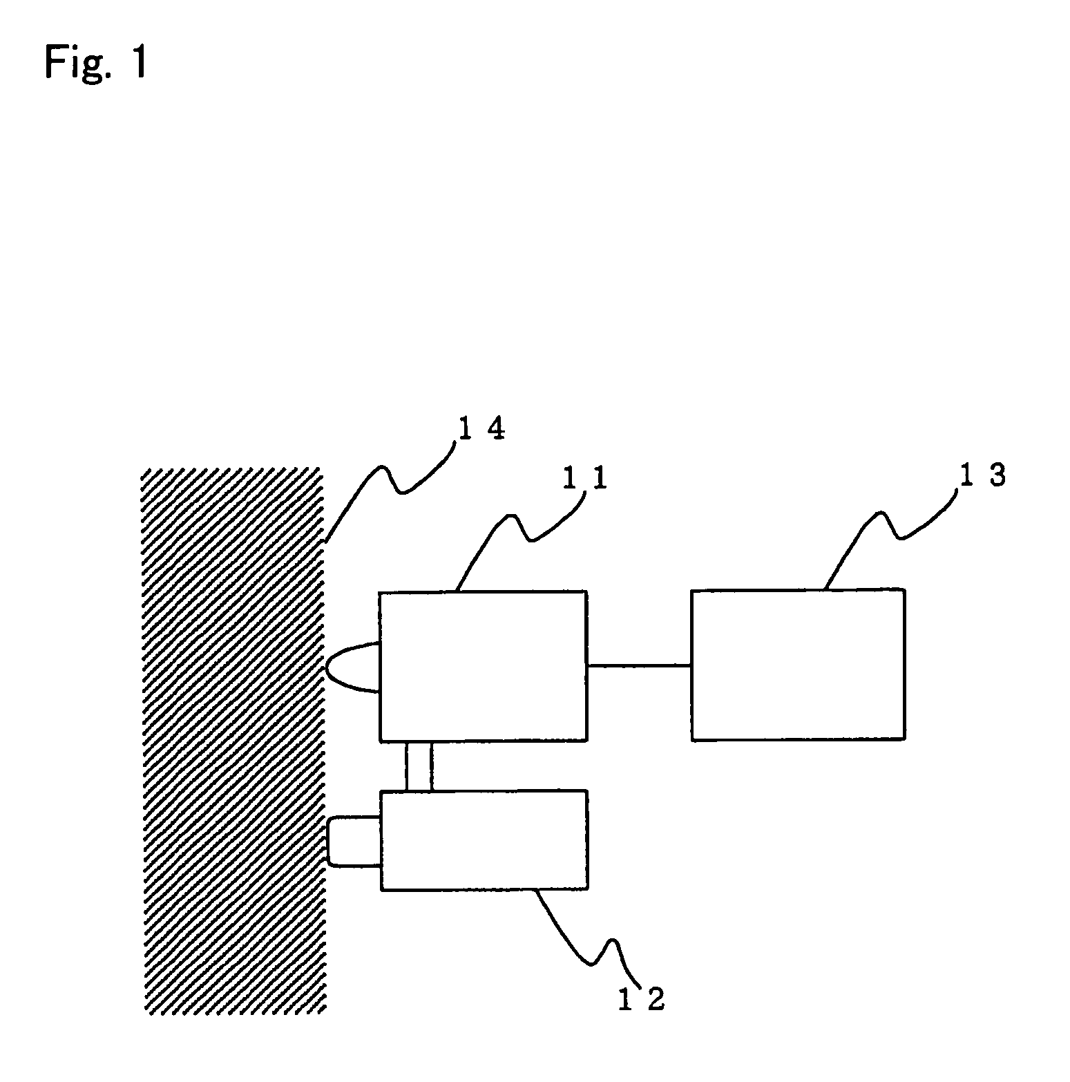
[0045]FIG. 1 is a block diagram illustrating the schematic construction of a structure diagnosis apparatus according to a first embodiment of the present invention. As shown in FIG. 1, the structure diagnosis apparatus according to the first embodiment includes a vibration detector 11 for detecting the vibration of a concrete structure 14, a vibration unit 12 by which vibration is applied to the concrete structure 14, and a display device 13 for displaying the vibration detected by the vibration detector 11.

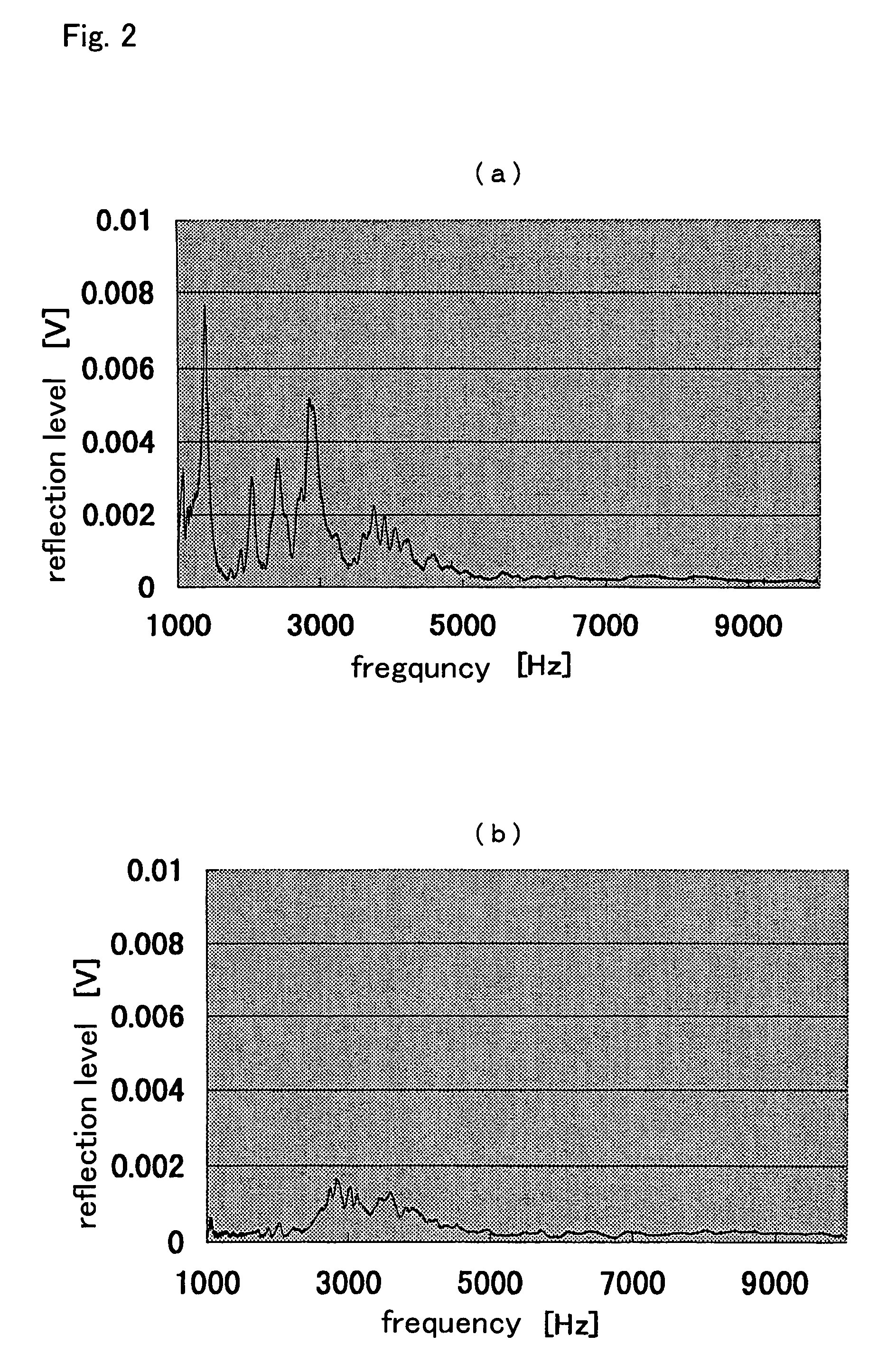
[0046]FIGS. 2(a) and 2(b) illustrate the vibration response conditions of the concrete structure 14 displayed by the display device 13, wherein FIG. 2(a) represents the vibration characteristic of a part having an internal defect, and FIG. 2(b) represents the vibration characteristic of a sound or normal part having no internal defect. FIG. 3 illustrates the vibration characteristic of the vibration detector 11.

[0047]FIG. 4(a), FIG. 4(b), FIG. 5(a) and FIG. 5(b) are views illustr...

embodiment 2

[0073]Hereinafter, reference will be made to a structure diagnosis method according to a second embodiment of the present invention while referring to FIGS. 11 through 13. FIG. 11 is a flow chart illustrating a method of diagnosing an internal defect in a concrete structure according to the present invention. FIG. 12 is a graph illustrating the amplitude levels of vibrations produced by vibrating a part having an internal defect and a part having no internal defect with application of a fixed force. FIG. 13 is a graph illustrating the relation between the amplitude levels of vibrations and the distances (depth) from a measuring surface to internal defects measured in a part where there exist internal defects.

[0074]The diagnosis of an internal defect in a concrete structure is carried out by using the above-mentioned structure diagnosis apparatus according to a procedure as shown in the flow chart of FIG. 11. First of all, it is determined whether a data base concerning the vibration...

embodiment 3

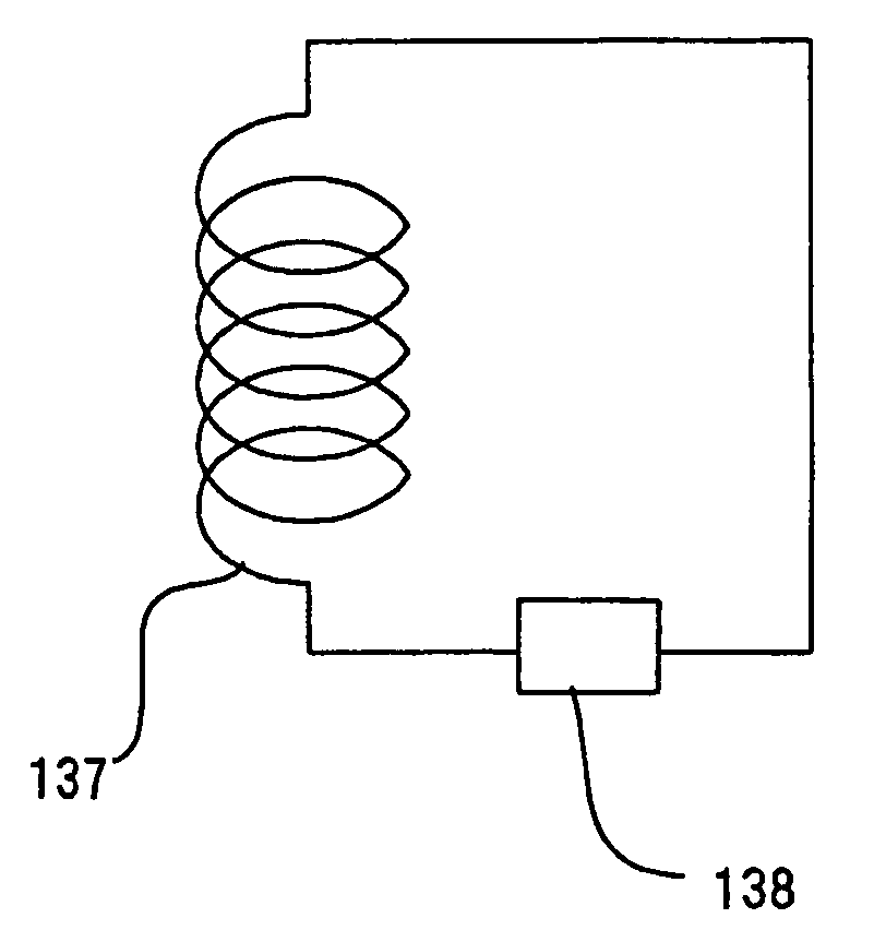
[0081]Hereinafter, reference will be made to a structure diagnosis apparatus according to a third embodiment of the present invention while referring to FIG. 14. FIG. 14 illustrates an example in which a vibration detector 11A is comprised of a plate spring, with the remaining construction of this embodiment being similar to that of the aforementioned first embodiment. In FIG. 14, a weight 111 is connected with a contactor or probe 113 through plate springs 112-2, and a coil 121 is wound around each of the plate springs 112-2 for converting a change in magnetic permeability into a corresponding electric signal. A vibration arriving at the contactor 113 is transmitted to the weight 111 through the plate springs 112-2. At this time, as illustrated in the aforementioned third embodiment, a resonance frequency fo determined by the spring constant k of each plate spring 112-2 and the mass M of the weight 111 is calculated by the above-mentioned formula (1).

[0082]The plate springs 112-2 a...


PUM


Abstract

An internal condition of a concrete structure is objectively evaluated irrespective of surrounding noise or the shape of a hammer, by placing a vibration sensor in direct contact with a measuring surface so as to directly convert a vibration generated on the measuring surface into a corresponding voltage without the intervention of a medium such as air thereby to quantify the vibration generated on the measuring surface concerned. A structure diagnosis apparatus of the present invention includes a vibration unit for generating an elastic wave in a measuring object of a concrete structure, a vibration detector adapted to be placed in contact with a surface of the measuring object for detecting a component in a predetermined frequency range of an elastic vibration generated on the surface of the measuring object by the vibration unit; and a display device for displaying a maximum amplitude of an output signal of the vibration detector.

Description

TECHNICAL FIELD[0001]The present invention relates to an apparatus for detecting abnormalities or defects in the interior of a concrete structure.BACKGROUND ART[0002]FIG. 17 illustrates a conventional apparatus, disclosed in Japanese Patent Application Laid-Open No. 7-20097 for instance, for detecting the sound pressure level of a hammering or striking sound by means of a sound pressure detector such as a microphone thereby to find an internal defect or flaw based on the sound pressure level thus detected. In FIG. 17, 2001 designates a concrete product, 2003 a hammer device having a hammer head 2002, and 2005 a fast Fourier transform machine connected with a sound level meter 2004 and a display device 2006.[0003]Now, reference will be made to the operation of the above-mentioned prior art. Conventionally, in such a destructive inspection, an inspector hits or strikes a measuring surface lightly with an inspection hammer so as to detect a defect, which may exist in the interior of a ...

Claims


Application Information

Patent Timeline
IPC IPC(8): G01N3/40G01N29/42G01N29/44G01N3/32G01N29/46G01M7/00G01N29/36G01N29/04G01N33/38G01N3/02G01N3/00G01N3/06
CPCG01M7/00G01N3/405G01N29/045G01N29/42G01N29/46G01N33/383G01N3/32G01N2291/102G01N2203/0039G01N2203/0062G01N2203/0284G01N2203/0617G01N2291/015G01N2291/0232G01N2291/02827
Inventor SHIMADA, TAKASHIMATSUHASHI, KANJI
Owner MITSUBISHI ELECTRIC CORP
Why Eureka
Try Eureka