Gas water heater and method of operation

a technology for gas water heaters and fuel, which is applied in the direction of heating types, lighting and heating apparatuses, instruments, etc., can solve the problems of insufficient use of electronic controls of gas water heaters, high cost of hot surface igniters, and inability to effectively control the temperature of water heaters, so as to improve efficiency and ensure the effect of constant temperatur

Inactive Publication Date: 2005-04-19
CLIFFORD TODD W
View PDF31 Cites 62 Cited by
  • Summary
  • Abstract
  • Description
  • Claims
  • Application Information

AI Technical Summary

Benefits of technology

[0014]The present invention provides gas water heater that is capable of maintaining a substantially constant temperature throughout the tank. The gas water heater of the present invention does not permit temperature stacking, that is, undesirably hot temperatures at an outlet of the water heater. In addition, the water heater of the present invention does not suffer from morning sickness, that is, undesirably cold temperatures at the outlet of the water heater. Therefore, the gas water heater of the present invention provides a substantially improved performance for the user and, in addition, operates with a significant improved efficiency.

Problems solved by technology

Gas water heaters have not extensively used electronic controls because of associated problems with electronic ignition systems and availability of an electrical outlet in close proximity to the water heater.
Hot surface igniters are expensive, easily broken and require a considerable amount of electrical energy to operate.
In comparison, spark igniters are inexpensive, durable and use little energy, however, the transient electrical pulses or voltage spikes from known spark ignition systems may undesirably interfere with electronic circuits.
Yet another obstacle in using an intelligent electronic control in gas water heaters is the availability of electricity in close proximity to the water heater.
The chassis, however, may not be properly grounded.
An ignition spark of this magnitude may cause transient electrical pulses or voltage spikes to undesirably interfere with the performance of electronic circuitry of the appliance.
For instance, the transient electrical pulses or voltage spikes may interfere with the performance of a microprocessor-based or microcontroller-based control circuit of an appliance.
In addition, the transient electrical pulses or voltage spikes may damage components of electric circuitry, may cause a microprocessor or microcontroller to incorrectly process information, and / or may cause electronic circuitry to lockup or crash.
Nevertheless, water or other conductive materials may gather on the insulating materials and short the electrodes to chassis ground and / or the electronic circuit.
In addition, cracks may develop in the insulating material.
As a result, water or other conductive materials may enter the cracks and short the electrodes to chassis ground and / or the electronic circuitry.
Besides being more costly and adding an additional component part to the appliance, the risk remains that transient electrical pulses or voltage spikes may reach the control through the cable assembly or other means.
First, the igniter elements is made of silicon carbide or other similar fragile materials that may easily break or be damaged during shipment.
Second, hot surface igniters may have a high field failure rate due to the igniter's elements burning out.
Third, hot surface igniters may cost approximately seven times more than a single electrode spark igniter.
Fourth, condensation shortens the life span of a hot surface igniter.
Finally, hot surface igniters require a significant amount of electrical current to operate.

Method used


Image

  • Gas water heater and method of operation
  • Gas water heater and method of operation
  • Gas water heater and method of operation

Examples


Embodiment Construction

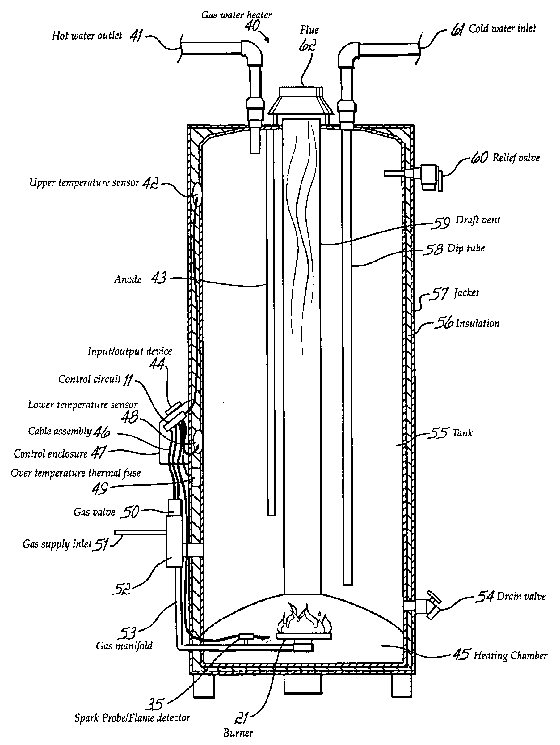
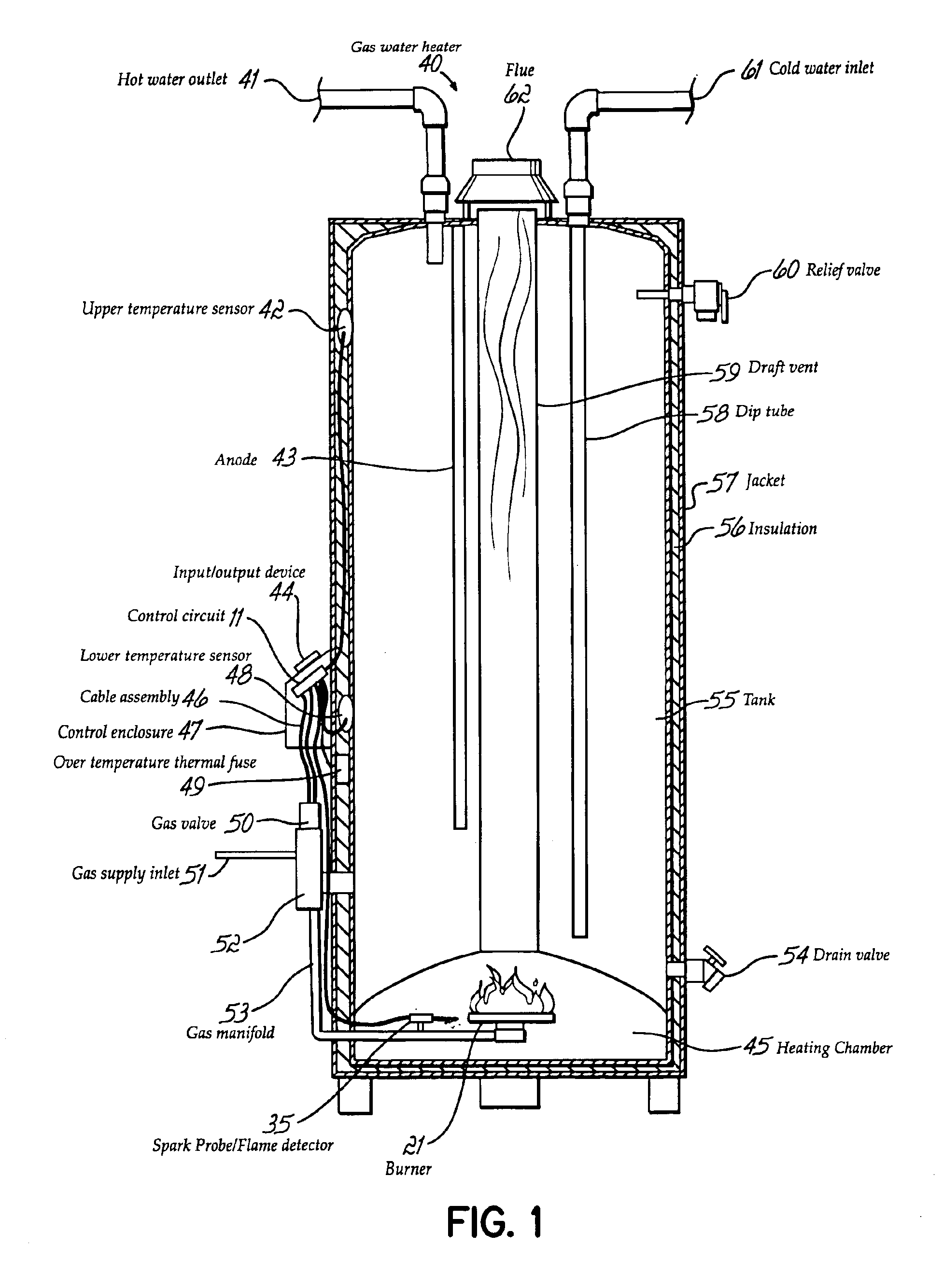
[0024]The present invention is directed to methods and devices for substantially reducing the stacking effect within a storage type gas water heater with the aid of multiple temperature sensors.

[0025]For example, the present invention is used for, or in conjunction with, practically any apparatus that is adapted to provide heat by igniting natural gas, propane gas, or practically any other fuel that is ignited to provide heat. In particular, the apparatus is a storage type residential gas water heater. The apparatus may also be a commercial water heater, boiler, or any other type of water heating appliance.

[0026]The ignition device is practically any device that is adapted to ignite fuel. For instance, the ignition device is a single electrode spark ignition system or a dual electrode spark ignition system. The ignition device may also be a hot surface igniter or standing pilot. The ignition device of the described embodiment is a single electrode spark ignition system.

[0027]As illu...


PUM


Abstract

A gas water heater with a tank for holding water including a gas valve mounted below the tank and in fluid communication with a supply of gas. A gas burner is fluidly connected to the gas valve. A first temperature sensor is mounted adjacent a lower portion of the tank and detects a temperature of the water in the lower portion of the tank, and a second temperature sensor is mounted adjacent an upper portion of the tank and detects a temperature of water in the upper portion of the tank. A control has inputs connected to the first and second temperature sensors and outputs connected to the gas valve. The control operates the gas valve in response to reading signals from the first and second temperature sensors such that water in the top and bottom portions of the tank stays within a desired temperature range.

Description

[0001]This application is a Continuation-in-Part of Ser. No. 09 / 840,587, filed on Apr. 23, 2001, Now U.S. Pat. No. 6,382,961, which is a Continuation of Ser. No. 09 / 594,544, filed on Jun. 14, 2000, now U.S. Pat. No. 6,220,854, which is a Division of Ser. No. 09 / 109,797, filed on Jul. 2, 1998, now U.S. Pat. No. 6,116,230, which is a Continuation-In-Part of Ser. No. 08 / 591,398, filed on Jan. 25, 1996, now U.S. Pat. No. 5,813,394, which is a Continuation-In-Part of Ser. No. 08 / 283,992, filed on Aug. 1, 1994, now U.S. Pat. No. 5,617,840, which is a Continuation-In-Part of Ser. No. 07 / 856,347, filed on Mar. 23, 1992, now U.S. Pat. No. 5,333,596.FIELD OF THE INVENTION[0002]The present invention relates generally to systems for igniting fuel and, more particularly, to a control system to improve the energy efficiency for a gas water heater.BACKGROUND OF THE INVENTION[0003]Gas water heaters have not extensively used electronic controls because of associated problems with electronic ignition...

Claims


Application Information

Patent Timeline
Patent Type & Authority Patents(United States)
IPC IPC(8): F22B5/00F23Q3/00
CPCF24H9/2035F24H1/205F24D2220/042F24D2220/08F24D2240/26F24H15/414F24H15/25F24H15/156F24H15/36F24H15/281F24H15/225F24H15/486F24H15/31F24H15/395F24H15/174F24H15/104
Inventor CLIFFORD, TODD W.
Owner CLIFFORD TODD W
Why Eureka
Try Eureka