
Method for resorting characteristics of polymer electrolyte fuel cell

a technology of polymer electrolyte and fuel cells, applied in the field of restoring the performance of fuel cells, can solve the problems of fuel gas occasionally contaminated, insufficient emulsification, inability to elute, etc., and achieve the effect of restoring cell performan

Inactive Publication Date: 2005-04-19
PANASONIC CORP
View PDF23 Cites 15 Cited by
  • Summary
  • Abstract
  • Description
  • Claims
  • Application Information

AI Technical Summary

Benefits of technology

[0012]The first embodiment is the method for restoring performance of the polymer electrolyte fuel cell that involves operating the polymer electrolyte fuel cell in a loaded current mode different from that of a normal operation for a predetermined time, thereby restoring the performance of the fuel cell.
[0014]The second embodiment is the method for restoring performance of the polymer electrolyte fuel cell that involves: supplying an oxidant gas and a fuel gas to the anode and the cathode respectively, while supplying the fuel gas to the anode and the oxidant gas to the cathode in the normal operation; and outputting a current from the cell body with the polarity being inverted, thereby restoring the performance of the fuel cell.
[0015]The third embodiment is the method for restoring performance of the polymer electrolyte fuel cell that involves supplying a pressurized gas to at least one of the cathode and the anode in an amount not less than 1.5 times as much as that in the normal operation or supplying oxygen to the cathode, thereby restoring the performance of the fuel cell.
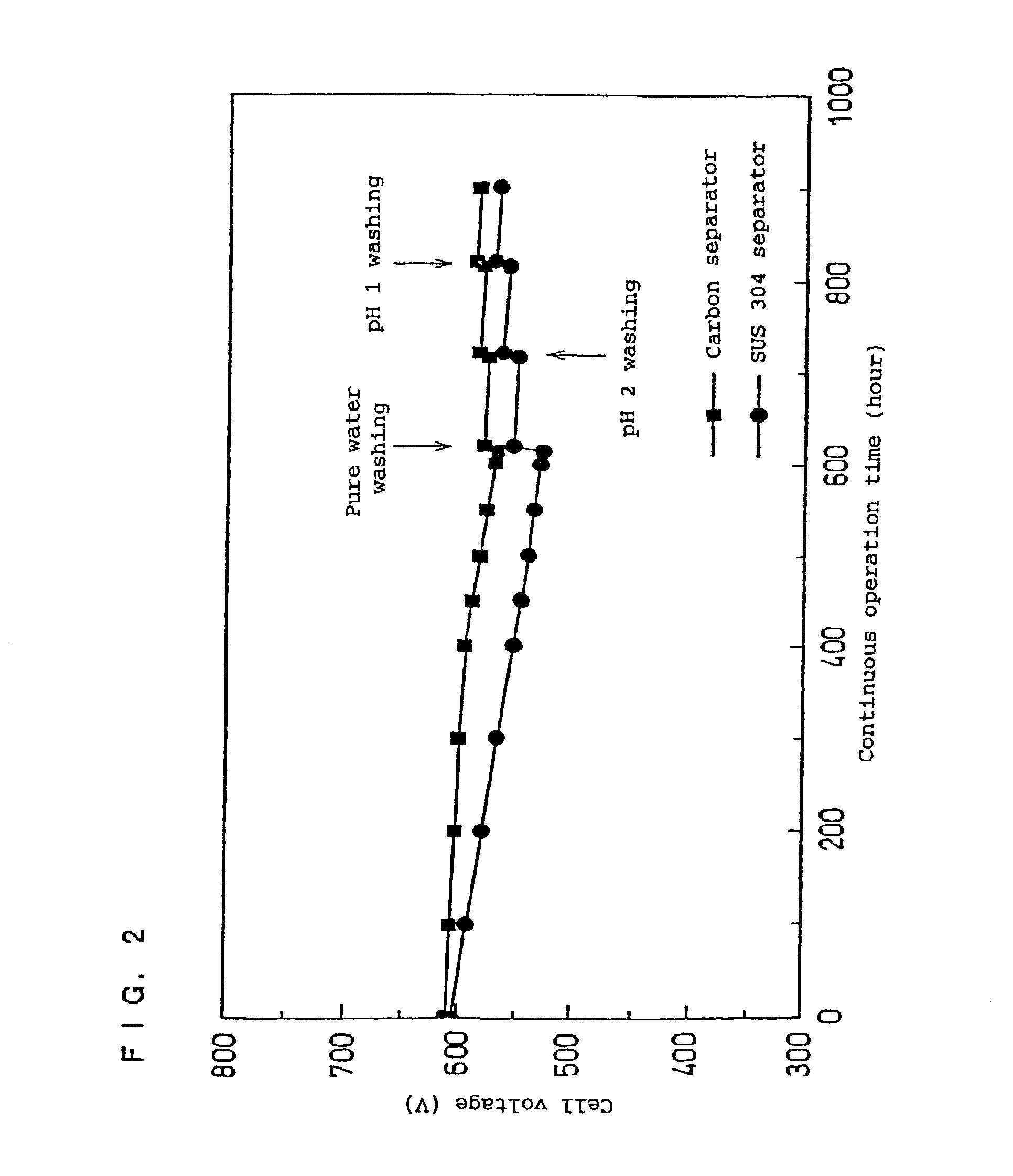
[0016]The fourth embodiment is the method for restoring the performance of the polymer electrolyte fuel cell that involves injecting a cleaning solution into the cathode and the anode through the gas flow path, thereby restoring the performance of the fuel cell.
[0019]According to the method for restoring the cell performance of the present invention, it is possible to discharge impurities accumulated in the cell body, such as contaminant ions, to the outside of the cell body.

Problems solved by technology

As a result, there is the possibility that ionic impurities, inorganic impurities and organic impurities contained in a carbon material, sealing material, resin material and metal material, each of which is the component of the cell, are eluted if the cell is operated for a long period of time.
Moreover, since air to be applied to the fuel cell contains, for example, trace amounts of air pollutants such as nitrogen oxides or sulfur oxides, the fuel gas is occasionally contaminated with traces amount of metal contained in the hydrogen generating device.
Further, such impurities are accumulated in the polymer electrolyte membrane, the catalyst layer at the electrode and the like, leading to a reduction in the conductivity of the polymer electrolyte as well as the catalytic activity.
This results in the problem that the cell performance is gradually degraded during a long operation of the fuel cell.
Additionally, in the case where a metal is used for the separator plate, metal ions eluted from the separator plate cause a further damage to the polymer electrolyte membrane and the catalyst layer.

Method used


Image

  • Method for resorting characteristics of polymer electrolyte fuel cell
  • Method for resorting characteristics of polymer electrolyte fuel cell
  • Method for resorting characteristics of polymer electrolyte fuel cell

Examples


examples 1 and 2

[0030]An acetylene black carbon powder carrying 25 wt% of platinum particles having a mean particle size of approximately 30 Å was used as a catalyst for electrode. A dispersion in which a powder of this catalyst was dispersed in isopropanol was mixed with a dispersion in which a powder of perfluorocarbon sulfonic acid was dispersed in ethyl alcohol, thereby obtaining a paste for catalyst layer.

[0031]Meanwhile, a carbon paper having a thickness of 300 μm was immersed in an aqueous dispersion of polytetrafluoroethylene (PTFE), and dried to obtain a water-repellent gas diffusion layer (porous electrode base material). The above-described paste for catalyst layer was applied onto one surface of this gas diffusion layer, which was then dried to obtain an electrode comprising a catalyst layer and the gas diffusion layer.

[0032]Next, a polymer electrolyte membrane was sandwiched by a pair of the above electrodes, with the catalyst layers facing inwardly, and the whole was hot-pressed at a ...

examples 3 and 4

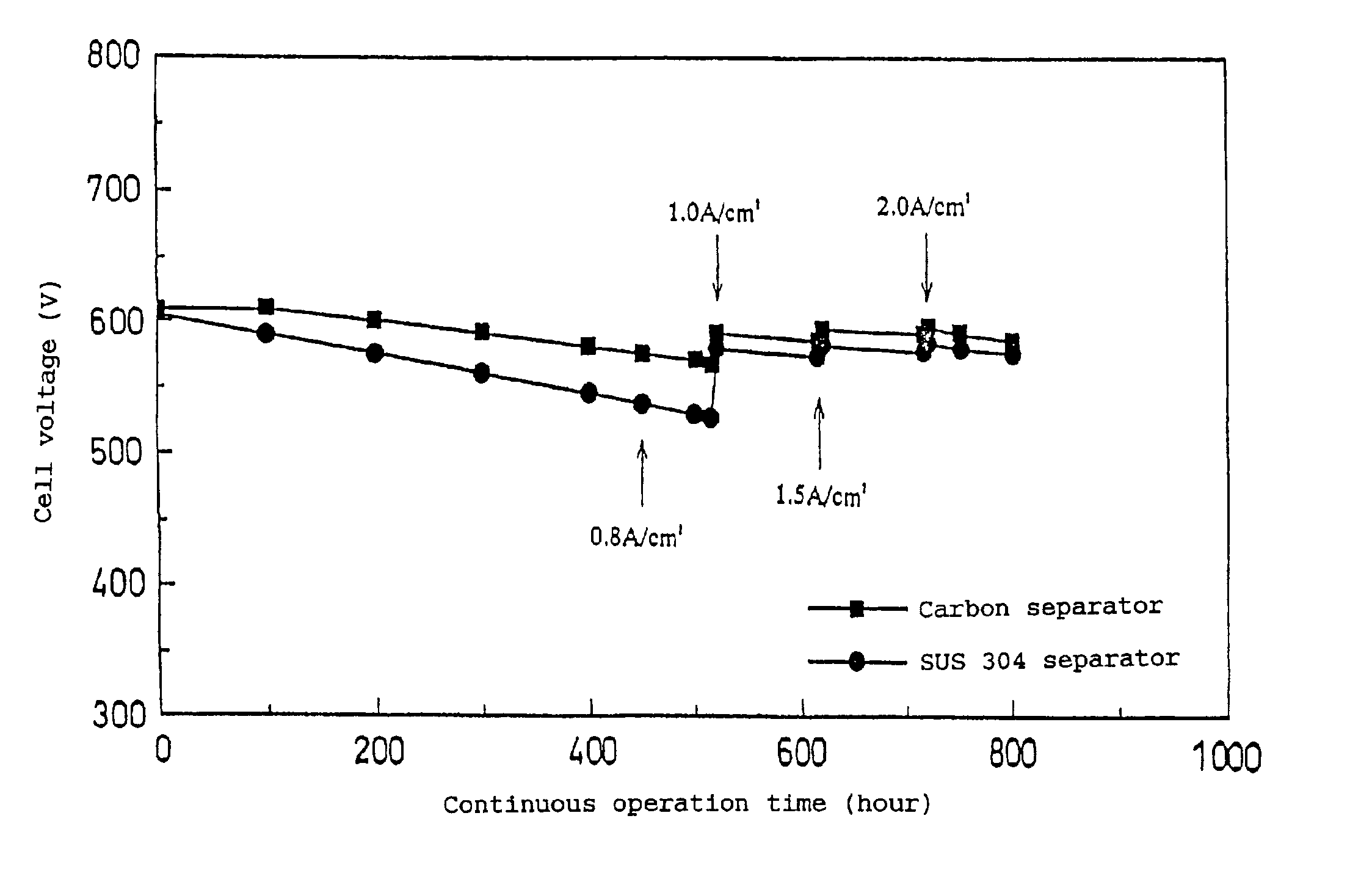
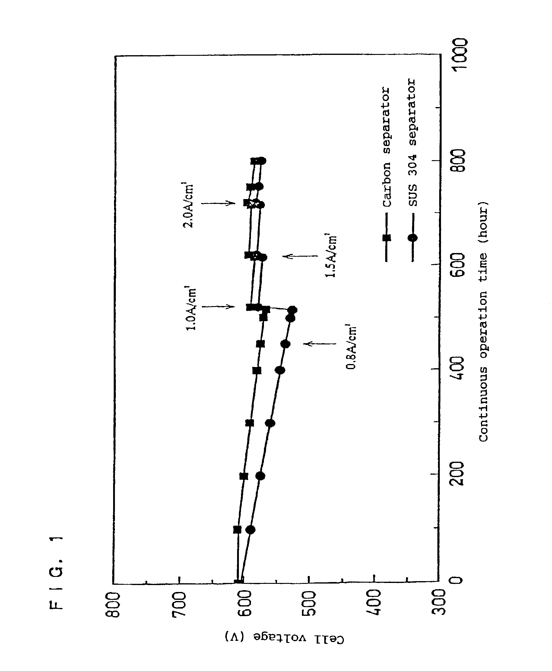
[0043]In the above Examples 1 and 2, it was confirmed that the object of the present invention could be achieved by changing the current density and thereby restoring the degraded performance of the fuel cell caused by the continuous operation.

[0044]In this example, a method for restoring the cell performance was conducted by increasing the loaded current to maintain the output voltage of each of fuel cells A and B, fabricated in the same manner as that used in Examples 1 and 2, at not more than 0.2 V for a predetermined time, and, thereafter, returning the operation to the normal mode.

[0045]As a result, it was also possible to restore the output voltage as described above by using this method.

examples 5 and 6

[0046]In the present examples, a method for restoring the dell performance was conducted by continuously operating each of fuel cells A and B, fabricated in the same manner as that used in Examples 1 and 2, for 500 hours, and reversing the direction of the output current after the cell voltage dropped.

[0047]More specifically, air was supplied to the anode side, to which hydrogen was supplied in the normal operation (output current=0.6 A / cm2), and hydrogen was supplied to the cathode side, to which air was supplied in the normal operation, and each cell was operated at 0.6 A / cm2 for 20 hours in this condition, with the direction of the output current being reversed. Thereafter, the operation was returned to the normal mode. By conducting such steps, the voltage of the fuel cell A using the carbon separator plate was restored, from 570 mV to 585 mV, and the voltage of the fuel cell B using the separator plate made of SUS 304 was restored, from 530 mV to 565 mV.

[0048]As described above...


PUM

PropertyMeasurementUnit
output voltageaaaaaaaaaa
thicknessaaaaaaaaaa
thicknessaaaaaaaaaa

Abstract

The present invention restores the performance of a fuel cell by: operating the cell in a loaded current mode different from that of a normal operation for a predetermined time; supplying an oxidant gas and a fuel gas to an anode and a cathode respectively and outputting a current from a cell body with the polarity being inverted; supplying a pressurized gas to at least one of the cathode and anode in an amount not less than 1.5 times as much as that in the normal operation or supplying oxygen to the cathode; or injecting a cleaning solution into the cathode and anode through a gas flow path. Consequently, it is possible to effectively restore a degraded performance of a polymer electrolyte fuel cell caused by a long operation.

Description

TECHNICAL FIELD[0001]The present invention relates to a method for restoring the performance of fuel cells useful as commercial cogeneration systems and power generating devices for mobile units, specifically, polymer electrolyte fuel cells using a polymer electrolyte.BACKGROUND ART[0002]Fuel cells cause a fuel gas such as hydrogen and an oxidant gas such as air to electrochemically react at a gas diffusion electrode, thereby concurrently supplying electricity and heat. Such fuel cells are classified into several types according to the kind of the electrolyte used therefor. The polymer electrolyte used herein generally comprises a skeleton of —CF2— as its main chain and a sulfonic acid is attached to the terminal of its side chain.[0003]A polymer electrolyte fuel cell is fabricated in the following manner. First, a paste for catalyst layer, prepared by mixing a dispersion of the above-described polymer electrolyte with a carbon powder carrying a platinum-based metal catalyst, is app...

Claims


Application Information

Patent Timeline
Patent Type & Authority Patents(United States)
IPC IPC(8): H01M8/04H01M8/06H01M8/02H01M8/10H01M8/24
CPCH01M8/04104H01M8/04223H01M8/0662H01M8/04679H01M8/0488Y02E60/50H01M8/04977H01M2300/0082H01M8/0491H01M8/0258H01M8/0267H01M8/241H01M8/043H01M8/04952H01M8/2483H01M8/02H01M8/0273
Inventor GYOTEN, HISAAKIKANBARA, TERUHISAUCHIDA, MAKOTOHATOH, KAZUHITOSAKAI, OSAMU
Owner PANASONIC CORP
Learn More