High speed fiber-optic attenuation modules

a variable optical attenuator, high-speed technology, applied in the direction of optical elements, multiplex communication, instruments, etc., can solve the problems of low dynamic range, low optical amplifier efficiency, non-uniform gain, etc., to achieve high dynamic range, low loss, and high power handling

a variable optical attenuator, high-speed technology, applied in the direction of optical elements, multiplex communication, instruments, etc., can solve the problems of low dynamic range, low optical amplifier efficiency, non-uniform gain, etc., to achieve high dynamic range, low loss, and high power handling

US6885807B2Inactive Publication Date: 2005-04-26NUONICS

Image

  • High speed fiber-optic attenuation modules
  • High speed fiber-optic attenuation modules
  • High speed fiber-optic attenuation modules

Examples


Embodiment Construction

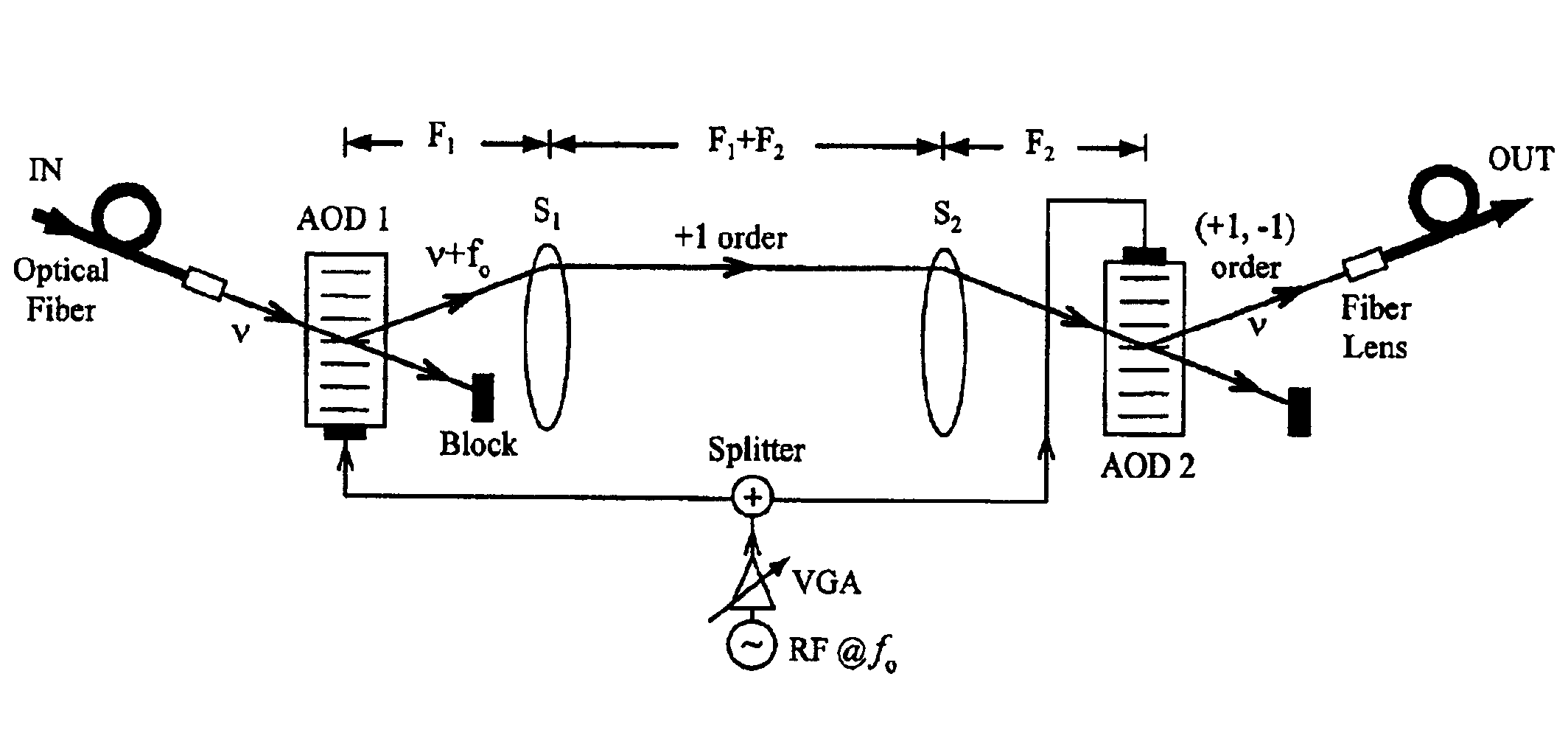
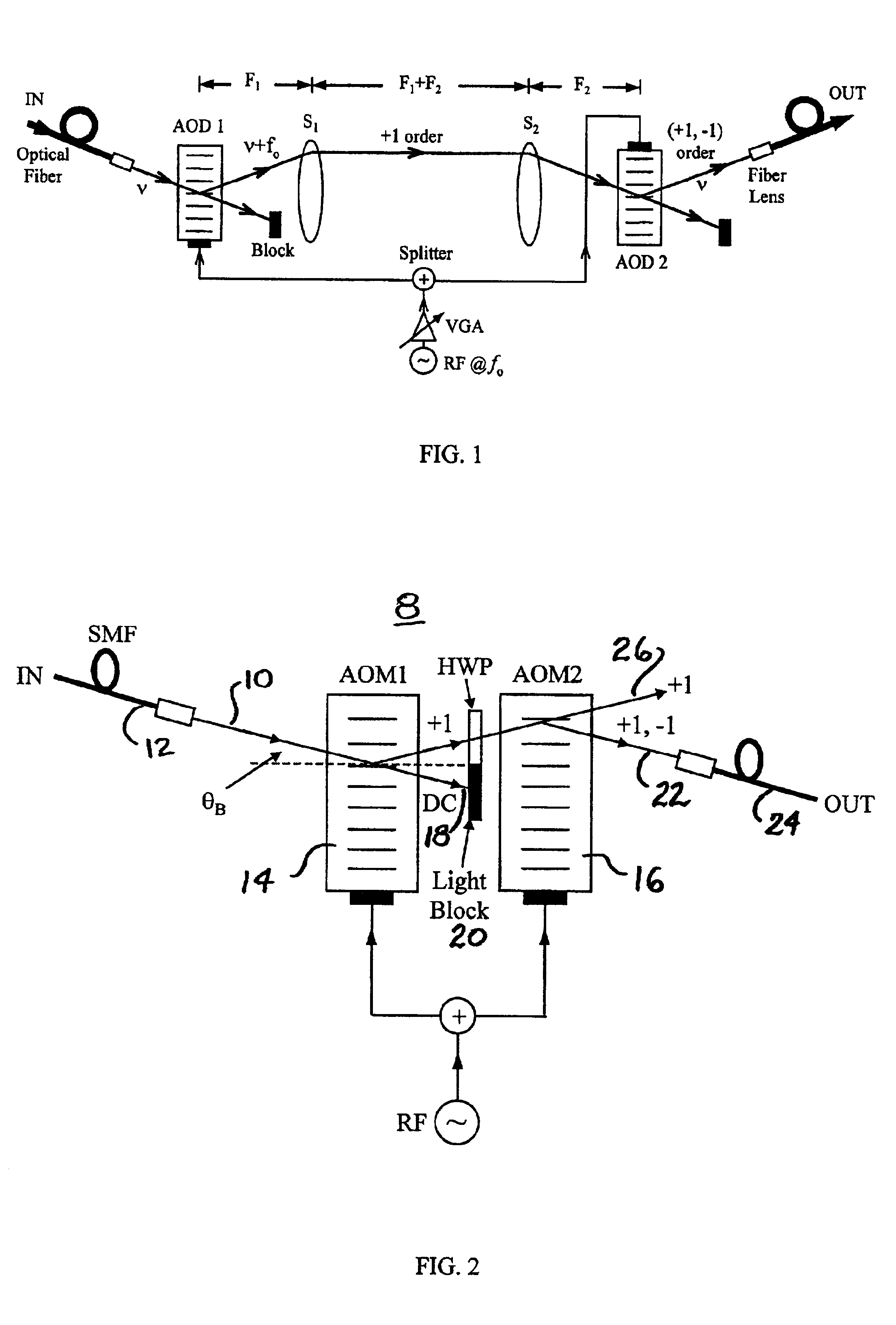
[0023]Optical attenuation via an AO device is controlled by varying the electrical drive power to the AO device that varies the AO device diffraction efficiency η. If two AO devices are used in cascade to form a doppler-free high dynamic range FO VOA as first proposed in N. A. Riza, “High speed fiber-optic switch,” U.S. Pat. No. 6,282,336, issued Aug. 28, 2001, and later in N. A. Riza and Z. Yaqoob, “High speed programmable optical attenuator,” SPIE Conf. Proc. Vol. 4046, Paper 10, April 26, Orlando, 2000, then essentially light undergoes a double diffraction effect leading to a η2 light efficiency control at the output of the module. This is the case when both AO devices are fed simultaneously by the same RF power and drive frequency. In dB or Decibel units, the squaring operation in diffraction efficiency leads to a multiply by two in dB, as dBs are a logarithmic to the base 10 scale. This refers to the doubling of the dynamic range and forms the basis for the present application ...


PUM

PropertyMeasurementUnit
incident angleaaaaaaaaaa
voltageaaaaaaaaaa
frequencyaaaaaaaaaa

Abstract

Unique multi-diffraction structures using electronically controlled Bragg diffraction devices such as acousto-optic (AO) devices to accomplish optical beam attenuation control functions. These variable optical attenuator (VOA) modules can be fully inertialess as they can use electronically programmable sub-microsecond speed AO devices to implement optical gain controls. These VOAs deliver desirable capabilities in one optically reversible unit, making high dynamic range, low loss, high power handling, ultra-fast, high optical isolation, broadband operation, self-aligning robust modules. These VOAs can be made essentially independent of the optical polarization of the incident light by the use of a unique fixed waveplate compensation technique within the VOA configuration that suppresses polarization dependent loss. Broadband gain control operation over several wavelengths can be achieved by controlling the frequency and electrical drive power of the chosen frequencies feeding the acousto-optic devices. Interleaver devices can be cascaded with the acousto-optic modules to improve wavelength selectivity of the overall VOA modules. Alternative embodiments can use electrically programmable Bragg gratings in polymer dispersed liquid crystal and acousto-optic tunable filter devices as Bragg grating devices. Embodiments are proposed using independently controlled Bragg diffractions using multiple drive signals connected to multiple device transducers. Drive signal formats can be digital, analog, or a combination for simultaneously driving the VOA modules. Dual-mode VOA module designs are also described using mirror positioning.

Description

SPECIFIC DATA RELATED TO THE INVENTION[0001]This application claims the benefit of U.S. patent application Ser. No. 60 / 275,792, filed on Mar. 14. 2001.FIELD OF INVENTION[0002]This invention relates to optical and fiber-optic (FO) variable optical attenuators (VOA) using electronically controlled Bragg-mode based light beam deflectors such as acousto-optic deflectors. The VOA structure can have several optical designs, all implementing the unique theme of multiple Bragg diffractions for optical gain or loss control of the incident optical beam. These basic no moving parts FO attenuator structures can be used for controlling the power in multiple light signals in optical networks such as wavelength division multiplexed (WDM) optical communications, distributed sensor networks, and photonic signal processing systems requiring gain control. The high speed, high isolation attenuators based on AO devices have the additional capability of handling high optical powers and can be used in opt...

Claims


Application Information

Patent Timeline
26 Apr 2005
Publication
US6885807B2
IPC
G02F1/11; G02F1/01; H04J14/02; H04B10/18
CPC
G02F1/11; H04B10/25073; H04J14/02; G02F2201/16; G02F2201/17; H04J14/0221; G02F2203/48
Inventors
RIZA, NABEEL AGHA