Apparatus for etching semiconductor samples and a source for providing a gas by sublimation thereto

a technology for etching apparatus and semiconductor samples, which is applied in the direction of microstructural devices, coatings, plasma techniques, etc., can solve the problems of forming a rate-limiting step in the etching process, the etching system is pulsed, and the nature of the system is cycli

Inactive Publication Date: 2005-05-03
SPTS TECH LTD
View PDF18 Cites 56 Cited by
  • Summary
  • Abstract
  • Description
  • Claims
  • Application Information

AI Technical Summary

Problems solved by technology

The largest drawback of the pulsed etch system described by Chu et al. relates to the cycling nature of the system.
Specifically, since the expansion chamber requires time to fill before the etch begins, is open to the main chamber during the etch, and is typically evacuated during the evacuation step of the cycle, it forms a rate-limiting step in the etching process.
This limitation, or bottleneck arises primarily from the time it takes to refill the expansion chamber with xenon difluoride gas after the evacuation step of the previous cycle.
The relatively expensive nature of xenon difluoride crystals makes this a major concern.
Furthermore, these continuous flow systems are much more sensitive to the geometry of the main chamber and to the placement of the xenon difluoride gas inlet hole(s) in the main chamber which may result in eddies in the flow of xenon difluoride gas.
Thus, the system described in Chu, et al. may not be attractive to these industries because it has an inherently high overhead.
However, raising the etching pressure in a system such as that described in Chu et al. may not be feasible. FIG. 2 is a graph of the xenon difluoride solid vapor pressure, wherein pressures above the curve at a particular temperature cause the vapor to solidify.
This is a critical limitation when the process is under full computer control, as found in semiconductor-type cluster tools, and visual inspection is not convenient or possible.

Method used


Image

  • Apparatus for etching semiconductor samples and a source for providing a gas by sublimation thereto
  • Apparatus for etching semiconductor samples and a source for providing a gas by sublimation thereto
  • Apparatus for etching semiconductor samples and a source for providing a gas by sublimation thereto

Examples


second embodiment

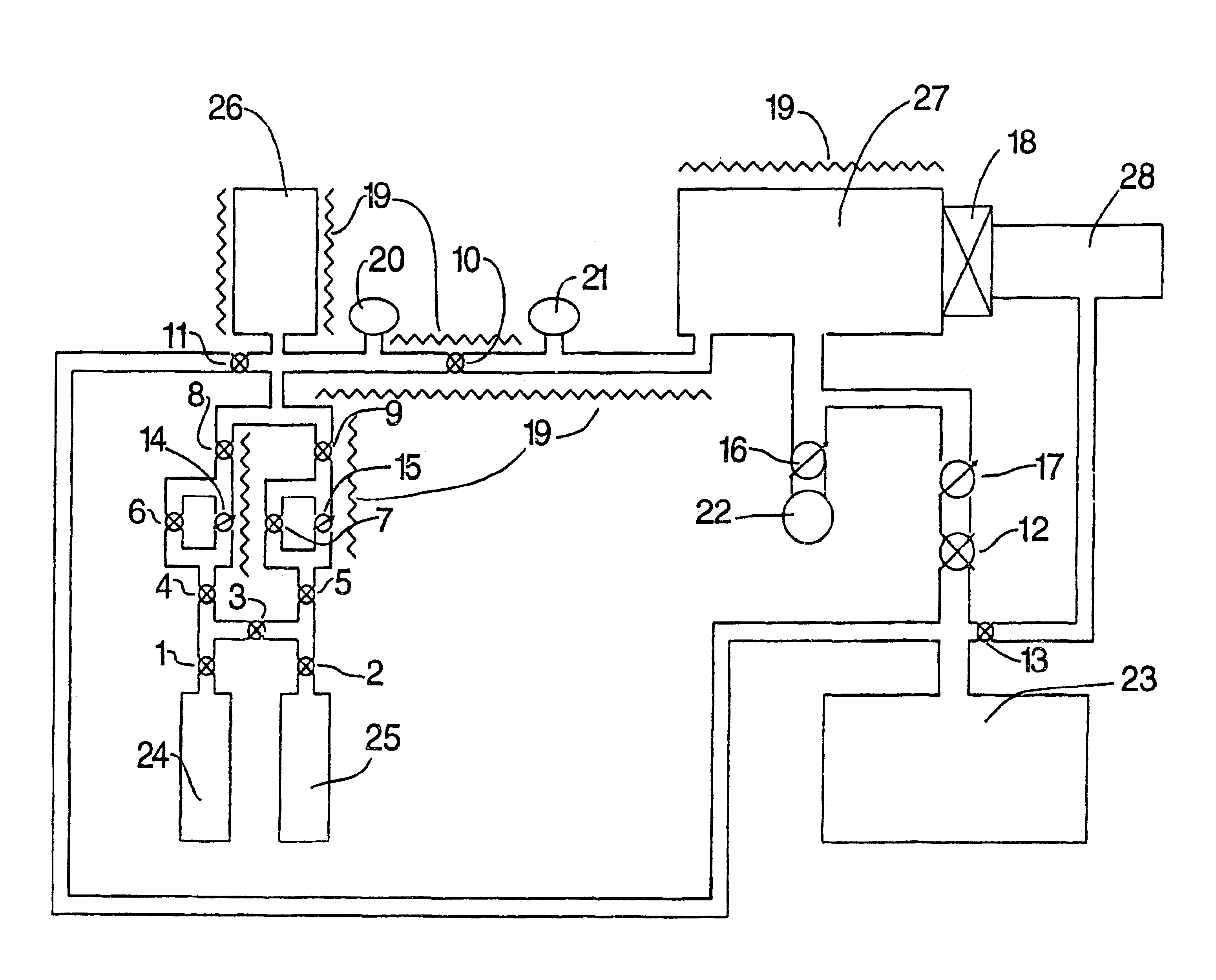
[0049]an apparatus according to the present invention is shown in FIG. 5. The apparatus shown in FIG. 5 includes second variable volume expansion chamber 30. Alternatively, variable volume expansion chambers 26 and 30 may be replaced by fixed volume expansion chambers having the same or different fixed volumes. The configuration shown in FIG. 5, whether using fixed or variable volume expansion chambers, allows for increased and variable capacity in terms of the amount of gas that can be transferred to etching chamber 27 during each cycle. Furthermore, if the expansion chambers shown in FIG. 5, whether fixed or variable volume, are each provided with separate fluid connections to sources 24 and 25, and if a separate fluid connection from expansion chambers to etching chamber 27 is provided, as is the case with the embodiment shown in FIG. 10, throughput may be increased by allowing one expansion chamber to fill while the other is being used to etch. Furthermore, additional expansion ...

third embodiment

[0050]Referring to FIG. 6, the present invention is shown that utilizes multiple fixed volume expansion chambers of different volumes. The embodiment shown in FIG. 6 includes three fixed volume expansion chambers 36A, 35B and 36C connected to the gas valving manifold through valves 33, 34 and 37. In addition, valves 31, 32 and 35 are provided to allow fixed volume expansion chambers 36A, 36B and 36C to be evacuated using roughing pump 23. Although three fixed volume expansion chambers are shown in FIG. 6, it is possible to use two fixed volume expansion chambers or four or more fixed volume expansion chambers. One very flexible combination of fixed volume expansion chambers is to have, for example, three fixed volume expansion chambers such as 36A, 36B and 36C, one of volume A, a second of volume 2 times A, and a third of volume 4 times A. This arrangement allows, through selecting different combinations of fixed volume expansion chambers, a range of total volume from A, 2A, 3A, 4A,...

fourth embodiment

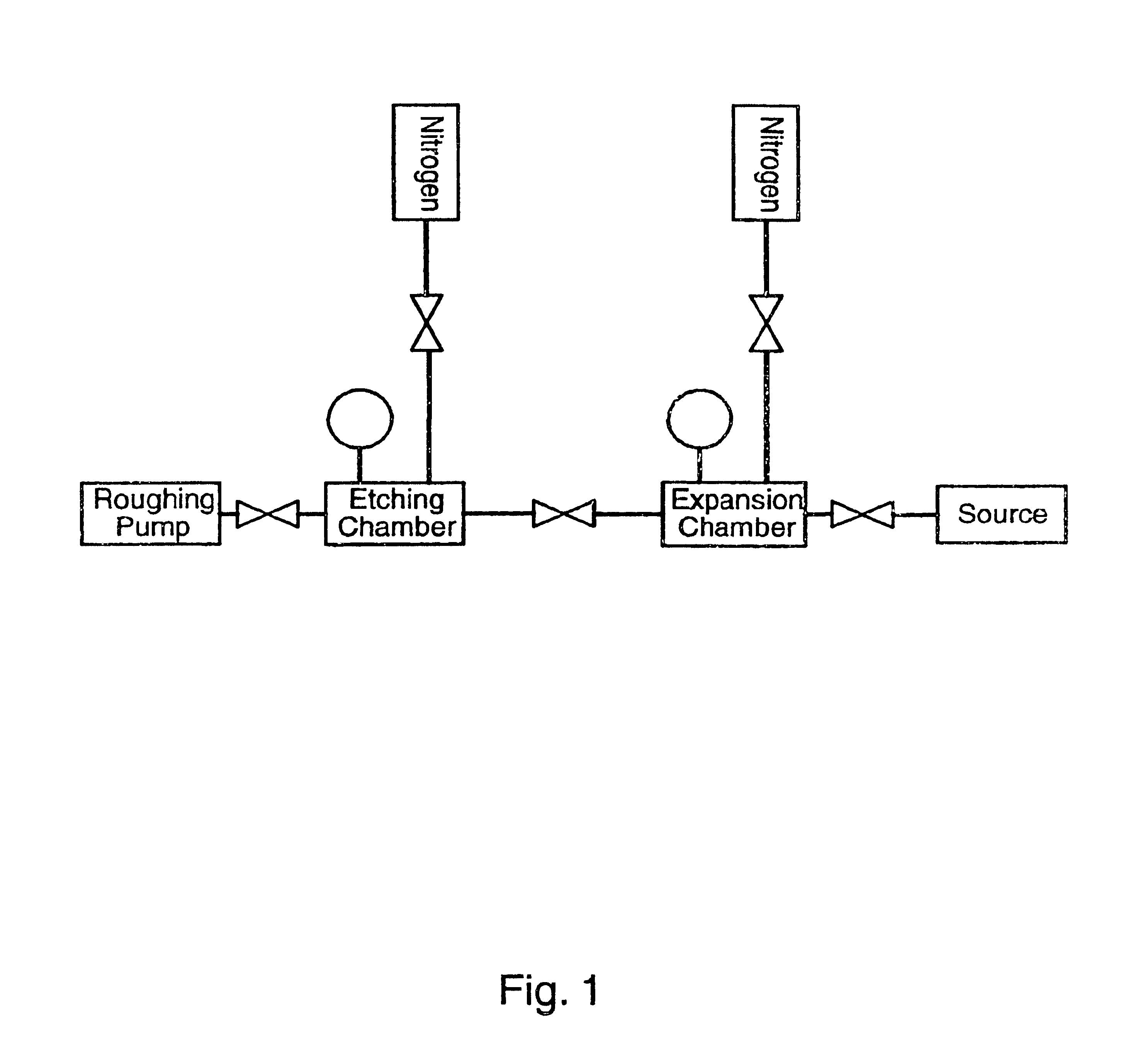
[0051]the apparatus configuration is shown in FIG. 7. The apparatus shown in FIG. 7 is similar to that shown in FIG. 3 except that load lock components 18, 28, and 13 have been removed. In many research applications, the ability to place the wafers directly into the etching chamber 27 is acceptable, and in some cases, preferred over the automated handling which accompanies a load lock system. Also, as shown in FIG. 7, an additional nitrogen source 24 and associated valve 40 are provided and are intended to be used for flushing the apparatus.

[0052]Referring to FIGS. 3, 5, 6 and 7, a residual gas analysis, or RGA, apparatus 22 may be used to determine when the etch process is complete. RGA apparatus 22 is connected to etching chamber 27 through variable inlet valve 16. RGA apparatuses are well known and generally comprise a mass spectrometer or quadrupole analyzer, vacuum valves, a real time calibration independent-type gas unit, a control valve, and an RGA control unit. The RGA contr...


PUM

PropertyMeasurementUnit
pressureaaaaaaaaaa
temperatureaaaaaaaaaa
pressureaaaaaaaaaa

Abstract

An etching apparatus for etching semi combustion samples may include one or more variable volume expansion chambers, two or more fixed volume expansion chambers, or combinations thereof in fluid communication with an etching chamber and a source of etching gas, such as xenon difluoride. The apparatus may further include a source of a mixing gas. An etching apparatus may also include a source of etching gas, an etching chamber in fluid communication with the source of etching gas, a flow controller connected between the source of etching gas and the etching chamber, and a vacuum pump in fluid communication with the etching chamber. A source for providing a gas by sublimation from a solid material is also provided, including a vacuum tight container and a mesh mounted in the interior of the vacuum tight container, wherein the mesh is adapted to receive and restrain the solid material.

Description

CROSS REFERENCE TO A RELATED APPLICATION[0001]This application claims the benefit of U.S. Provisional Application No. 60 / 233,512 filed on Sep. 19, 2000.FIELD OF THE INVENTION[0002]The present invention relates to an apparatus for etching semiconductor samples. More particularly, the present invention relates to an apparatus for etching semiconductor samples having a variable volume expansion chamber and to an apparatus having two or more fixed volume expansion chambers, wherein either apparatus may include an apparatus for detecting the end point of the etching process. The present invention also relates to an improved source for providing a gas by sublimation, in particular a source for providing a gas by sublimation to an apparatus described herein.BACKGROUND AND DESCRIPTION OF THE PRIOR ART[0003]The etching of silicon by xenon difluoride is well known. Xenon difluoride requires no external energy sources or ion bombardment to etch silicon, and it exhibits high selectivity to many...

Claims


Application Information

Patent Timeline
Patent Type & Authority Patents(United States)
IPC IPC(8): H01J37/32B81C1/00C23F4/00H01L21/302
CPCH01J37/32458H01J37/3244H01L21/306
Inventor LEBOUITZ, KYLE S.MIGLIUOLO, MICHELE
Owner SPTS TECH LTD
Why Eureka
Try Eureka