Methods and apparatus for fluid distribution in microfluidic systems

a microfluidic system and fluid distribution technology, applied in the field of combinatorial chemistry, can solve the problems of not being incorporated into a system suitable for large-scale combinatorial chemistry research, or even moderate-scale combinatorial materials science research, and the application of chemical microreactors to specific research and commercial goals, and achieves a large degree of analytical flexibility and is inexpensively manufactured.

Inactive Publication Date: 2005-05-10
FREESLATE
View PDF125 Cites 36 Cited by
  • Summary
  • Abstract
  • Description
  • Claims
  • Application Information

AI Technical Summary

Benefits of technology

[0009]It is also an object of the invention to provide chemical processing microsystems that are relatively inexpensive to manufacture and use, that are flexible as to applications and variations, and that provide results which are scaleable to commercially significant systems.
[0022]For such methods, the candidate materials can be loaded simultaneously, or alternatively sequentially into the four or more microreactors. In preferred approaches, the candidate materials are loaded without affecting the structural integrity of a fluid distribution system through which the one or more reactants are supplied to the microreactors or through which one or more reactor effluents are discharged from the microreactors.
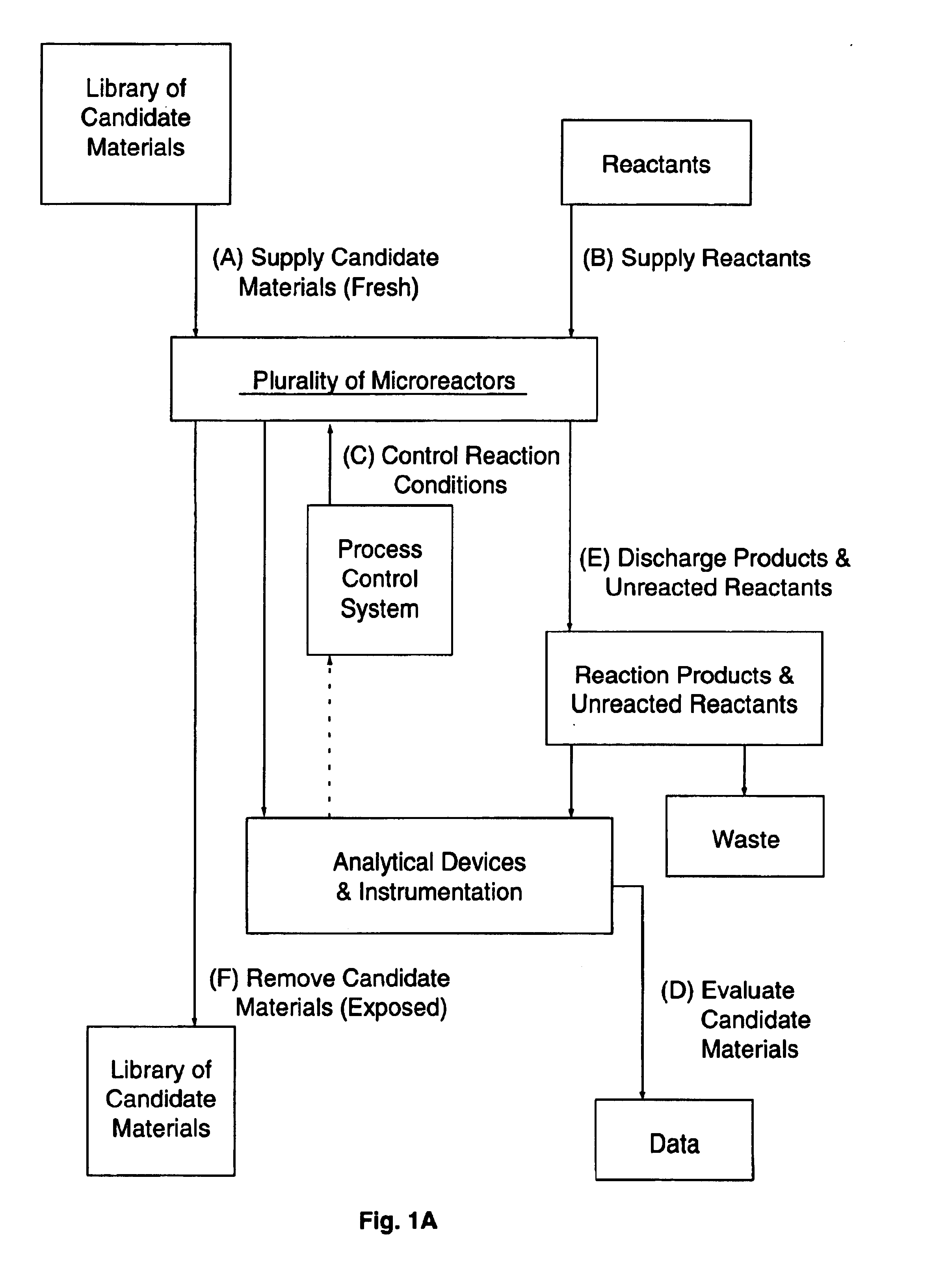
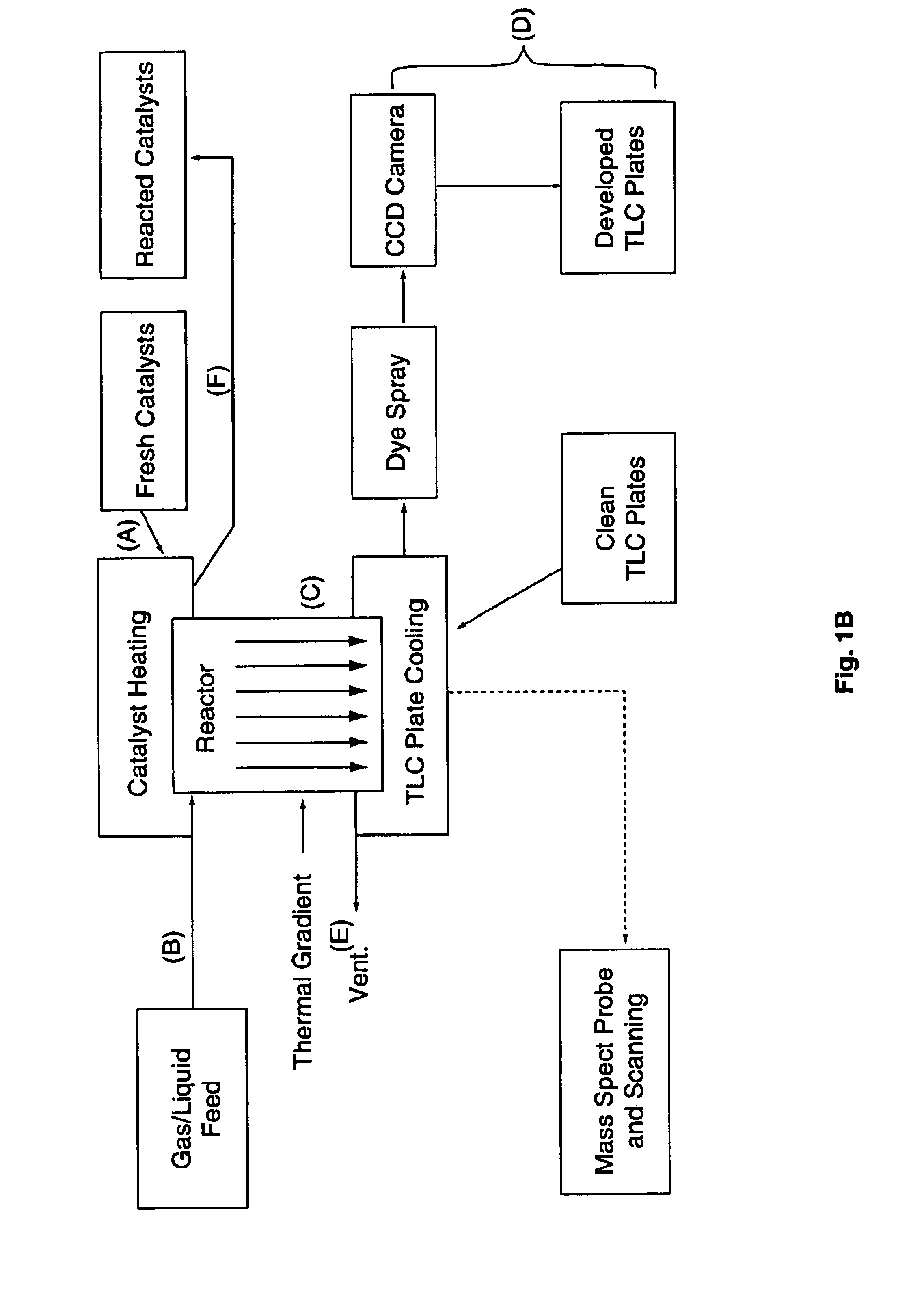
[0032]As such, the devices, systems, and methods of the present invention offer distinct advantages over the prior art. The chemical processing microsystems of the present invention provide efficient means for loading and unloading candidate materials being evaluated, for supplying reactants to a plurality of microreactors, for controlling of the reaction conditions in a plurality of microreactors, and for evaluating the candidate materials for specific properties of interest (e.g., catalytic activity). Additionally, the instant chemical processing microsystems can be employed for screening candidate materials such as catalysts with very high-throughput and with a large degree of analytical flexibility. Moreover, the chemical processing microsystems of the invention require only a small amount of candidate materials relative to known systems, yet offer catalyst contact times that are generally representative of those employed in production-scale reactors. Advantageously, the contact-time distribution is, for one embodiment of microreactors, broader than the distribution associated with known microreactor designs, and is, therefore, better suited to a combinatorial primary screen than known designs. Additionally, the chemical processing microsystems of the present invention can be relatively inexpensively manufactured using commercially available technologies.

Problems solved by technology

Although such high-throughput synthesis and screening methodologies are conceptually promising, substantial technical challenges exist for application thereof to specific research and commercial goals.
While combinatorial chemistry applications have been contemplated, the various chemical microreactor designs reported to date, however, have not been incorporated into systems suitable for large-scale, or even moderate-scale, combinatorial chemistry research, and particularly, for combinatorial material science research directed to heterogeneous catalyst screening for identification and / or optimization.
), none of these reactors are satisfactory for combinatorial materials science applications.
These and other microreactor designs known in the art do not address important concerns such as the loading, and / or unloading of larger numbers of candidate materials (e.g., catalysts) for screening, the supplying of reactants to a plurality of microreactors, the controlling of the reaction conditions in a plurality of microreactors, and / or the evaluating of candidate materials for specific properties of interest (e.g., catalytic activity).
Known microreactors also have common limitations, for example, with respect to a low throughput (e.g., the number of catalysts that can be screened over a given period of time), a narrow distribution of heterogeneous catalyst contact times, a large amount of each (often expensive) candidate catalyst required to effect the chemical conversion, the potential inherent negative influence of microreactor materials on a reaction of interest, a high degree of complexity, a lack of flexibility for analyzing the results of the chemical conversion, and, in some cases, a lack of scalability of research results to production-scale systems.

Method used


Image

  • Methods and apparatus for fluid distribution in microfluidic systems
  • Methods and apparatus for fluid distribution in microfluidic systems
  • Methods and apparatus for fluid distribution in microfluidic systems

Examples


example 1

Manufacture of Microreactor / Microseparator

[0213]A chemical processing microsystem, substantially as shown and described in connection with FIGS. 18A and 18B, was manufactured as follows. The microsystem can be used, for example, to identify potential heterogeneous catalysts for the direct amination of benzene to aniline.

Reactor Block Array

[0214]A first silicon / glass laminae substructure comprising 256 reactor block wells, a fluid supply manifold / flow restrictor substantially as shown and described in connection with FIG. 7B, and a reactor effluent channel for fluid communication with an effluent manifold was formed. The laminae substructure was fabricated from one 4″ diameter double polished p-type Si(001) wafer (International Wafer Service) and one Pyrex 7740 glass wafer (Corning) using standard microprocessing technology.

[0215]Fluid distribution components (supply manifold and reactor effluent channels) were formed in the silicon wafer. Briefly, the silicon wafer was coated with 5...

example 2

Operation of Parallel Microreactor / Microseparator

Catalyst Synthesis

[0225]Catalysts were formed using various methods known in the art and / or described herein (See, especially, the examples in above-referenced, co-pending patent application U.S. Ser. No. commonly-owned co-pending U.S. patent application Ser. No. 09 / 516,669, filed Mar. 1, 2000 by Lugmair et al. Chemical compositions of the catalyst libraries were generated interactively using LIBRARY STUDIO™ (Symyx Technologies, Inc.) library design software, together with automated liquid handling equipment (Cavro Scientific Instruments, Inc.) under software control of IMPRESSIONIST™ (Symyx Technologies, Inc). Briefly, catalysts were formed in 4 mm diameter wells on a 3″×3″ square glass or quartz wafer. For impregnation synthesis, slurried catalyst carriers were arrayed into the wells with a liquid handling robot. The slurries were dried and prefabricated support wafers were stored until needed for catalyst library synthesis. The cat...


PUM

PropertyMeasurementUnit
hydraulic radiusaaaaaaaaaa
volumeaaaaaaaaaa
volumeaaaaaaaaaa

Abstract

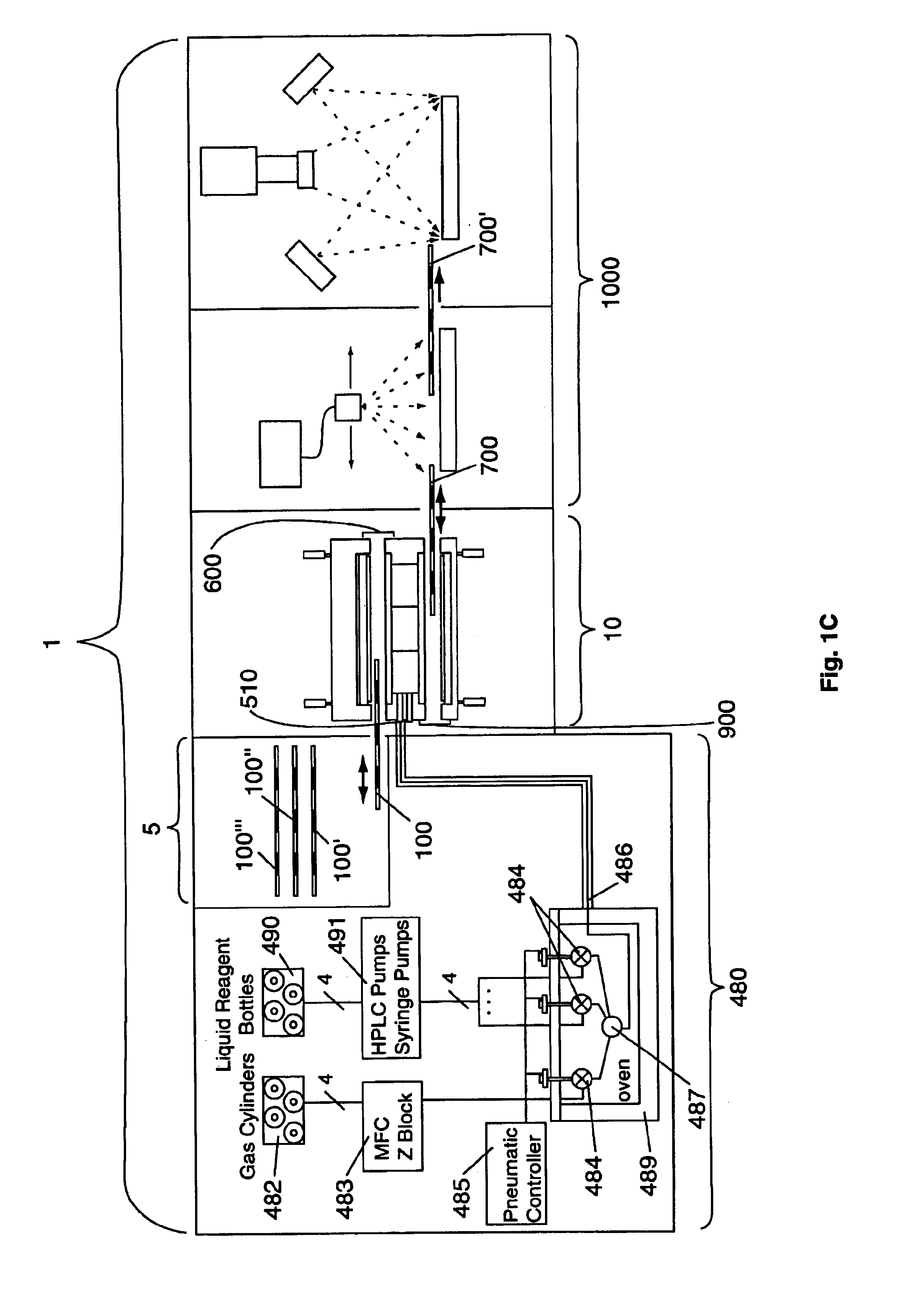
A chemical processing microsystem useful for identifying and optimizing materials (e.g., catalysts) that enhance chemical processes or for characterizing and / or optimizing chemical processes is disclosed. The chemical processing microsystem comprises a plurality of microreactors 600 and, in a preferred embodiment, a plurality of microseparators 900 integral with the chemical processing microsystem 10. The microreactors 600 are preferably diffusion-mixed microreactors formed in a plurality of laminae that include a modular, interchangeable candidate-material array 100. The material array 100 comprises a plurality of different candidate materials (e.g., catalysts), preferably arranged at separate, individually addressable portions of a substrate (e.g., wafer). The microseparators 900 are similarly formed in a plurality of laminae that include a modular, interchangeable adsorbent array 700. The adsorbent array 700 comprises one or more adsorbents, preferably arranged at separate, individually addressable portions of a substrate to spatially correspond to the plurality of different candidate materials. Modular microfluidic distribution systems are also disclosed. The chemical processing microsystem can be integrated into a material evaluation system that enables a comprehensive combinatorial material science research program.

Description

[0001]This application is a divisional application of co-pending U.S. patent application Ser. No. 09 / 518,794 filed Mar. 3, 2000, which itself claims priority to commonly owned, co-pending U.S. patent application Ser. No. 60 / 122,704 filed Mar. 3, 1999 entitled “Chemical Processing Microsystems, Diffusion-Mixed Microreactors and Methods for Preparing and Using Same”, which is hereby incorporated by reference for all purposes.BACKGROUND OF THE INVENTION[0002]The present invention relates generally to the field of combinatorial chemistry and, in preferred applications, to the field of combinatorial materials science. In particular, the invention relates to systems and methods employing microfluidic devices in chemical processes, for characterizing and optimizing such chemical processes and for identifying materials that enhance such chemical processes. Preferred embodiments of the invention relate to microchemical processing systems, to diffusion-mixed microreactors, and to methods for ...

Claims


Application Information

Patent Timeline
Patent Type & Authority Patents(United States)
IPC IPC(8): B01L3/00B01L7/00B01J19/00C01B3/00C01B3/40C07C17/23C07C45/00C07C45/35C07C45/38C07C45/34C07C45/54C07C45/72C07C17/00C07C45/46C07C45/50G01N31/10B01F5/06G01N30/90G01N30/00G01N35/00G01N35/02C40B30/08C40B40/18
CPCB01F15/0264B01J19/0046B01J19/0093B01L3/5025B01L3/5027B01L3/502707B01L3/502715B01L7/54C01B3/40C07C17/23C07C45/34C07C45/35C07C45/38C07C45/46C07C45/54C07C45/72G01N31/10C07C47/06C07C47/22C07C47/04C07C47/127C07C49/403B01F5/0601B01J2219/00286B01J2219/00306B01J2219/00308B01J2219/00313B01J2219/00317B01J2219/00337B01J2219/00351B01J2219/00353B01J2219/00389B01J2219/00418B01J2219/00452B01J2219/00479B01J2219/00495B01J2219/00585B01J2219/00596B01J2219/00605B01J2219/0061B01J2219/00612B01J2219/00621B01J2219/00626B01J2219/00635B01J2219/00637B01J2219/00641B01J2219/00657B01J2219/00659B01J2219/00704B01J2219/00707B01J2219/0072B01J2219/00745B01J2219/00747B01J2219/00759B01L2200/0689B01L2200/146B01L2300/0864B01L2300/0874B01L2300/0887B01L2300/14B01L2300/18B01L2400/0487C40B30/08C40B40/18G01N30/90G01N35/028G01N2035/00158Y10T436/2575Y10T436/117497Y10T436/118339G01N30/466Y10T137/87885B01F25/41B01F35/7182
Inventor BERGH, H. SAMGUAN, SHENHENG
Owner FREESLATE
Why Eureka
Try Eureka