Refractive projection objective for immersion lithography

a technology of refractive projection and objective, which is applied in the direction of photomechanical equipment, instruments, printers, etc., can solve the problems that the optical system may not be suitable for series production of semiconductors, and achieve the effect of high numerical aperture and good correction sta

Inactive Publication Date: 2005-05-10
CARL ZEISS SMT GMBH
View PDF20 Cites 188 Cited by
  • Summary
  • Abstract
  • Description
  • Claims
  • Application Information

AI Technical Summary

Benefits of technology

[0012]It is one object of the invention to provide a refractive projection objective which is suitable for immersion lithography and which has, in conjunction with a moderate overall size,

Problems solved by technology

The optical system may not be suitable for use in t

Method used


Image

  • Refractive projection objective for immersion lithography
  • Refractive projection objective for immersion lithography
  • Refractive projection objective for immersion lithography

Examples


Embodiment Construction

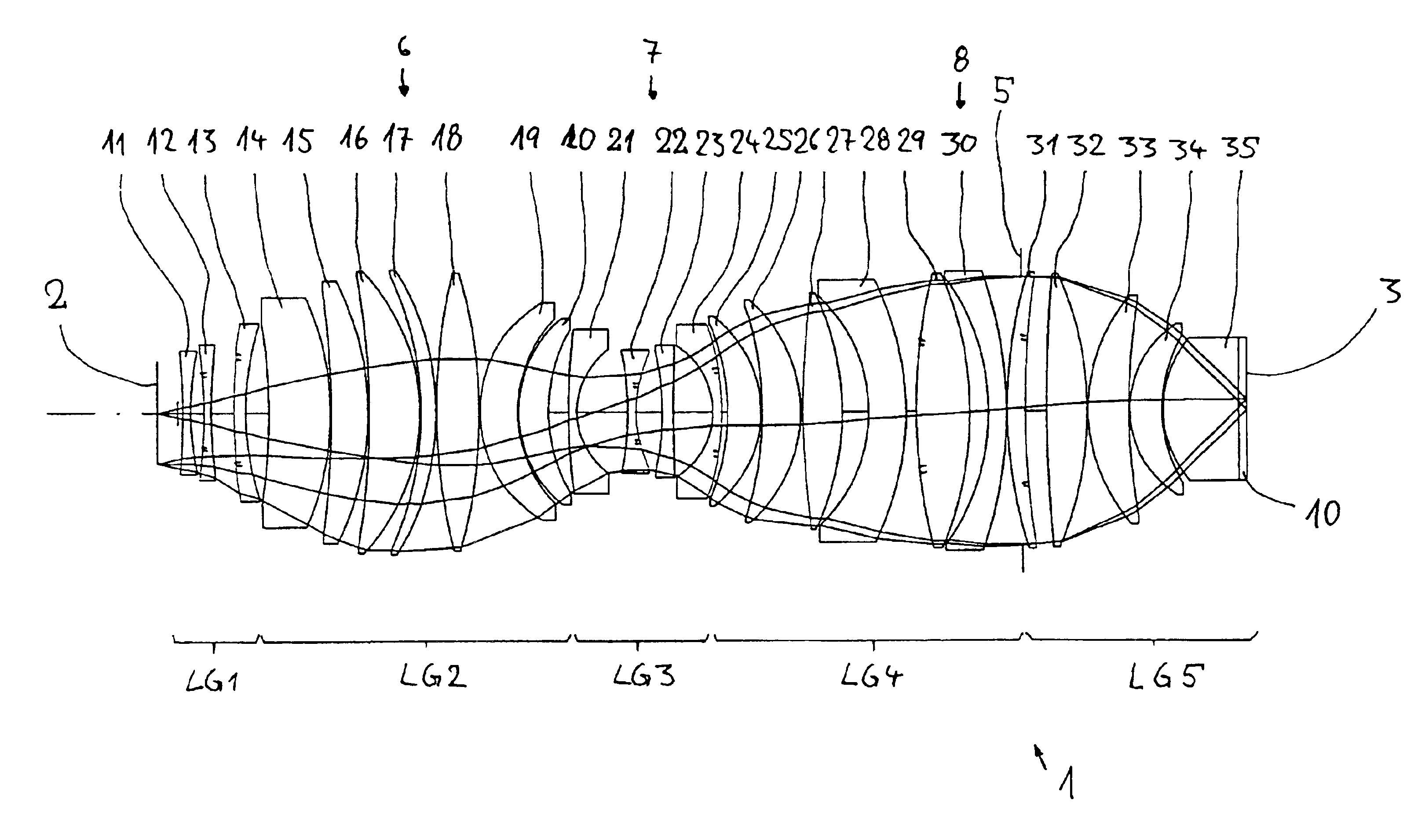
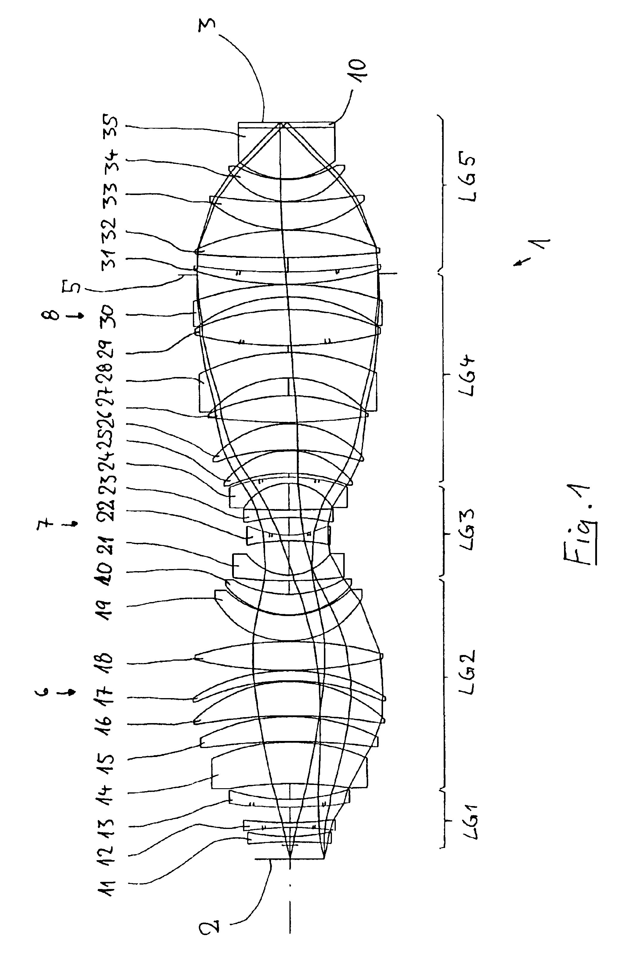
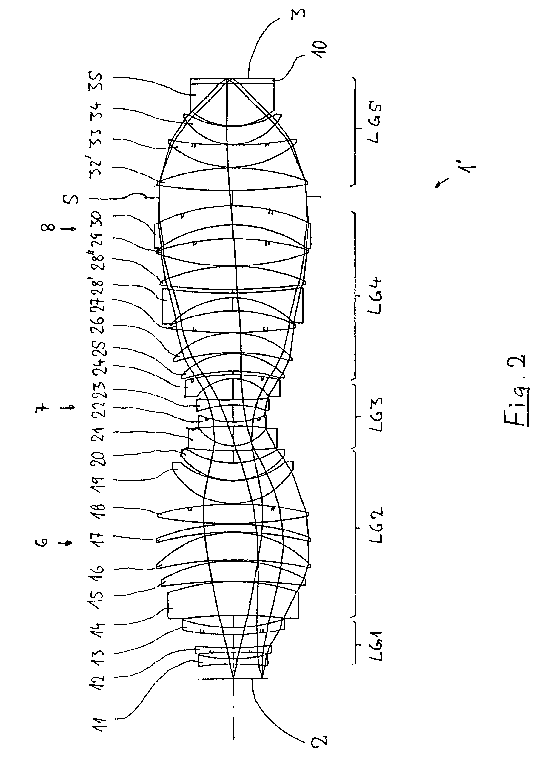
[0039]In the following description of preferred embodiments, the term “optical axis” denotes a straight line through the centers of curvature of the optical components. Directions and distances are described as on the image side or towards the image when they are aligned in the direction of the image plane or the substrate, which is to be exposed, located there, and as on the object side or towards the object when they are directed towards the object with reference to the optical axis. In the examples, the object is a mask (reticle) with the pattern of an integrated circuit, but it can also be another pattern, for example a grating. In the examples, the image is formed on a wafer which serves as a substrate and is provided with a photoresist layer, but other substrates are also possible for example elements for liquid crystal displays or substrates for optical gratings. The focal lengths specified are focal lengths with reference to air.

[0040]Identical or mutually corresponding feat...


PUM


Abstract

A purely refractive projection objective suitable for immersion micro-lithography is designed as a single-waist system with five lens groups, in the case of which a first lens group with a negative refracting power, a second lens group with a positive refracting power, a third lens group with a negative refracting power, a fourth lens group with a positive refracting power and a fifth lens group with a positive refracting power are provided. The system aperture is in the region of maximum beam diameter between the fourth and the fifth lens group. Embodiments of projection objectives according to the invention achieve a very high numerical aperture of NA>1 in conjunction with a large image field, and are distinguished by a good optical correction state and moderate overall size. Pattern widths substantially below 100 nm can be resolved when immersion fluids are used between the projection objective and substrate in the case of operating wavelengths below 200 nm.

Description

[0001]The following disclosure is based on German Patent Application No. DE 102 10 899.4 filed on Mar. 8, 2002, which is incorporated into this application by reference.BACKGROUND OF THE INVENTION[0002]1. Field of the Invention[0003]The invention relates to a refractive projection objective for projecting a pattern arranged in an object plane of the projection objective into an image plane of the projection objective with the aid of an immersion medium which is arranged between a last optical element of the projection objective and the image plane.[0004]2. Description of the Related Art[0005]Photo-lithographic projection objectives have been in use for several decades for producing semiconductor components and other finely structured structural elements. They serve the purpose of projecting patterns of photomasks or reticles, which are also denoted below as masks or reticles, onto an object coated with a photosensitive layer with very high resolution on a reducing scale.[0006]Three ...

Claims


Application Information

Patent Timeline
IPC IPC(8): G03F7/20G02B13/14G02B13/18G02B13/24H01L21/027
CPCG02B13/143G03F7/70341G03F7/70241G02B13/24G03F7/20G02B9/60
Inventor ROSTALSKI, HANS-JUERGENULRICH, WILHELM
Owner CARL ZEISS SMT GMBH
Why Eureka
Try Eureka