Formation of a field reversed configuration for magnetic and electrostatic confinement of plasma

a field reverse configuration and plasma technology, applied in nuclear reactors, nuclear engineering, greenhouse gas reduction, etc., can solve the problems of low efficiency (less than 30%), high radioactivity, and structural damage to the reactor walls, and achieve the effect of facilitating classical containment of electrons and ions

Inactive Publication Date: 2005-05-10
RGT UNIV OF CALIFORNIA
View PDF22 Cites 99 Cited by
  • Summary
  • Abstract
  • Description
  • Claims
  • Application Information

AI Technical Summary

Benefits of technology

[0016]To address the problems faced by previous plasma containment systems, a system and apparatus for containing plasma are herein described in which plasma ions are contained magnetically in stable, large orbits and electrons are contained electrostatically in an energy well. A major innovation of the present invention over all previous work with FRCs is the simultaneous electrostatic confinement of electrons and magnetic confinement of ions, which tends to avoid anomalous transport and facilitate classical containment of both electrons and ions. In this configuration, ions may have adequate density and temperature so that upon collisions they are fused together by the nuclear force, thus releasing fusion energy.

Problems solved by technology

The disadvantages of neutronic reactions are that (1) the flux of fast neutrons creates many problems, including structural damage of the reactor walls and high levels of radioactivity for most construction materials; and (2) the energy of fast neutrons is collected by converting their thermal energy to electric energy, which is very inefficient (less than 30%).
The advanced fuels have disadvantages, too.
Also, it is much more difficult to cause the advanced fuels to fuse.
Electrons, however, have a much smaller gyroradius, so they respond to the fluctuations and transport anomalously.
A Tokamak reactor using D-T fuel has the additional problem that most of the energy of the fusion products energy is carried by 14 MeV neutrons, which cause radiation damage and induce reactivity in almost all construction materials due to the neutron flux.
In addition, the conversion of their energy into electricity must be by a thermal process, which is not more than 30% efficient.
Producing useful fusion reactions in this type of reactor has been infeasible because the background plasma slows down the ion beams.
In none of these devices, however, does an equilibrium electric field play any part.
None of these patents consider electrostatic confinement of electrons and magnetic confinement of ions.
Although there have been many research projects on electrostatic confinement of ions, none of them have succeeded in establishing the required electrostatic fields when the ions have the required density for a fusion reactor.
Lastly, none of the patents cited above discuss a field reversed configuration magnetic topology.

Method used


Image

  • Formation of a field reversed configuration for magnetic and electrostatic confinement of plasma
  • Formation of a field reversed configuration for magnetic and electrostatic confinement of plasma
  • Formation of a field reversed configuration for magnetic and electrostatic confinement of plasma

Examples


experiment 1

Propagating and Trapping of a Neutralized Beam in a Magnetic Containment Vessel to Create an FRC

[0187]Beam propagation and trapping were successfully demonstrated at the following parameter levels:

[0188]Vacuum chamber dimensions: about 1 m diameter, 1.5 m length.

[0189]Betatron coil radius of 10 cm.

[0190]Plasma beam orbit radius of 20 cm.

[0191]Mean kinetic energy of streaming beam plasma was measured to be about 100 eV, with a density of about 1013 cm−3, kinetic temperature on the order of 10 eV and a pulse-length of about 20 μs.

[0192]Mean magnetic field produced in the trapping volume was around 100 Gauss, with a ramp-up period of 150 μs. Source: Outer coils and betatron coils.

[0193]Neutralizing background plasma (substantially Hydrogen gas) was characterized by a mean density of about 1013 cm−3, kinetic temperature of less than 10 eV.

[0194]The beam was generated in a deflagration type plasma gun. The plasma beam source was neutral Hydrogen gas, which was injected through the back o...

experiment 2

FRC Formation Utilizing the Combined Beam / Betatron Formation Technique

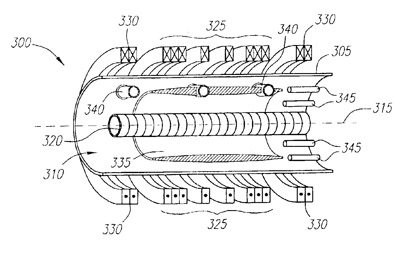
[0198]FRC formation was successfully demonstrated utilizing the combined beam / betatron formation technique. The combined beam / betatron formation technique was performed experimentally in a chamber 1 m in diameter and 1.5 m in length using an externally applied magnetic field of up to 500 G, a magnetic field from the betatron flux coil 320 of up to 5 kG, and a vacuum of 1.2×10⁻⁵ torr. In the experiment, the background plasma had a density of 1013 cm−3 and the ion beam was a neutralized Hydrogen beam having a density of 1.2×1013 cm−3, a velocity of 2×107 cm / s, and a pulse length of around 20 μs (at half height). Field reversal was observed.

experiment 3

FRC Formation Utilizing the Betatron Formation Technique

[0199]FRC formation utilizing the betatron formation technique was successfully demonstrated at the following parameter levels:

[0200]Vacuum chamber dimensions: about 1 m diameter, 1.5 m length.

[0201]Betatron coil radius of 10 cm.

[0202]Plasma orbit radius of 20 cm.

[0203]Mean external magnetic field produced in the vacuum chamber was up to 100 Gauss, with a ramp-up period of 150 μs and a mirror ratio of 2 to 1. (Source: Outer coils and betatron coils).

[0204]The background plasma (substantially Hydrogen gas) was characterized by a mean density of about 1013 cm−3, kinetic temperature of less than 10 eV.

[0205]The lifetime of the configuration was limited by the total energy stored in the experiment and generally was around 30 μs.

[0206]The experiments proceeded by first injecting a background plasma layer by two sets of coaxial cable guns mounted in a circular fashion inside the chamber. Each collection of 8 guns was mounted on one o...


PUM


Abstract

A system and method for containing plasma and forming a Field Reversed Configuration (FRC) magnetic topology are described in which plasma ions are contained magnetically in stable, non-adiabatic orbits in the FRC. Further, the electrons are contained electrostatically in a deep energy well, created by tuning an externally applied magnetic field. The simultaneous electrostatic confinement of electrons and magnetic confinement of ions avoids anomalous transport and facilitates classical containment of both electrons and ions. In this configuration, ions and electrons may have adequate density and temperature so that upon collisions they are fused together by nuclear force, thus releasing fusion energy. Moreover, the fusion fuel plasmas that can be used with the present confinement system and method are not limited to neutronic fuels only, but also advantageously include advanced fuels.

Description

CROSS-REFERENCE TO RELATED APPLICATION[0001]This application is a continuation of U.S. Ser. No. 10 / 066,424, filed Jan. 31, 2002, now U.S. Pat. No. 6,664,740, which claims the benefit of provisional U.S. application Ser. No. 60 / 266,074, filed Feb. 1, 2001, and provisional U.S. application Ser. No. 60 / 297,086, filed on Jun. 8, 2001, which applications are fully incorporated herein by reference.FIELD OF THE INVENTION[0002]The invention relates generally to the field of plasma physics, and, in particular, to methods and apparati for confining plasma. Plasma confinement is particularly of interest for the purpose of enabling a nuclear fusion reaction.BACKGROUND OF THE INVENTION[0003]Fusion is the process by which two light nuclei combine to form a heavier one. The fusion process releases a tremendous amount of energy in the form of fast moving particles. Because atomic nuclei are positively charged—due to the protons contained therein—there is a repulsive electrostatic, or Coulomb, force...

Claims


Application Information

Patent Timeline
Patent Type & Authority Patents(United States)
IPC IPC(8): G21D7/00G21B1/11H05H1/02H05H1/12G21B1/00G21B1/05H05H1/16
CPCG21B1/052G21D7/00H05H1/16H05H1/03H05H1/14Y02E30/122G21B1/05H05H1/12Y02E30/10Y02E30/00H05H1/02H05H1/10
Inventor ROSTOKER, NORMANBINDERBAUER, MICHLGARATE, EUSEBIOBYSTRITSKII, VITALY
Owner RGT UNIV OF CALIFORNIA
Why Eureka
Try Eureka