Structure of chip type electrolytic capacitor

a technology of electrolytic capacitors and structures, applied in the direction of fixed capacitors, casings/cabinets/drawers, electrical equipment casings/cabinets/drawers, etc., can solve the problems of soldering problems, capacitors cannot function correctly, /b> may still be polluted, etc., to increase the airtightness of capacitors, prevent pollution of lead pins, and simple structure

Inactive Publication Date: 2005-05-24
GEMMY ELECTRONICS
View PDF5 Cites 20 Cited by
  • Summary
  • Abstract
  • Description
  • Claims
  • Application Information

AI Technical Summary

Benefits of technology

[0009]Accordingly, the primary object of the present invention is to provide a slim chip type electrolytic capacitor, wherein a simple structure is used to increase the airtight of capacitor, prevent pollution on lead pins, and to simplify production process to enhance yield rate.
[0010]A casing cover is made by plastic injection machine using high strength engineering plastic. An aluminum foil, lead pins, and an insulation paper are assembled to a dielectric. The dielectric is installed into the casing cover, and electrolyte is metered filled in. A glue dispenser moving control system applies a multipoint dispensing of mechatronics and control technology to achieve high-speed gluing with no burr and no surplus glue to clean up required. A low viscosity liquid multipoint metered filling / vacuum technology enhances speed of electrolyte adsorption to fill the bill of requirement for mass production. A supersonic welding and an epoxide adhesive solidification package technology replace rubber packing with. The Epoxide is heatproof and shrink-resistant in solidification so that the epoxide can seal completely and prevent leaking of electrolyte. This skill of the art can enhance airtight and reduce volume of chip type electrolytic capacitor to anti shock and electrolyte leaking.

Problems solved by technology

The capacitor cannot be functioned correctly.
Also, The lead pins 121 may be polluted with the prior filled electrolyte and cause soldering problems.
Although this method can improve sealing to solve problem of foregoing prior art, but the lead pins 221 may still be polluted with the prior filled electrolyte.
This skill although may replace said elastomer 230 and simplify process, but the resin glue may shrink in solidification and cause leak, and heat-unstable may also cause deformed.

Method used


Image

  • Structure of chip type electrolytic capacitor
  • Structure of chip type electrolytic capacitor
  • Structure of chip type electrolytic capacitor

Examples


first embodiment

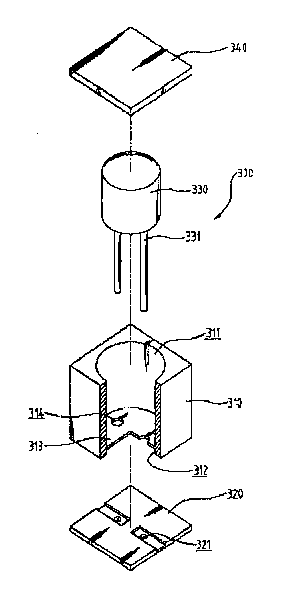
[0025]Referring to FIG. 2, the present invention will be described. An electrolytic capacitor 330 comprises:

[0026]A casing cover 310 with a partition 313 inside to separate the casing cover 310 into a dielectric chamber 311 and a buffer chamber 312. The partition 313 has two holes 314 for lead pins 331 of dielectric 330 pass through. The dielectric chamber 311 receives the dielectric 330, and has a rabbet 315 on open side to fix with a top cover 340. Thereby, the dielectric 330 may be set in the dielectric chamber 311 and lead pins 331 can pass through the two holes 314 on the partition 313, then fill with electrolysis in the dielectric chamber 311 so that the lead pins 331 won't be polluted.

[0027]A bottom cover 320 covers the buffer chamber 312 to seal, and has two holes 321 for the lead pins 331 of the dielectric 330. On the outside of the bottom cover 320 has chamfer 322. A stuff of epoxide 316 is filled with into the buffer chamber 312 to fix the dielectric 330 and improve stren...

second embodiment

[0031]FIG. 6 is an exploded perspective view of the second embodiment in the present invention. An electrolytic capacitor 400 comprises:

[0032]A casing cover 410 with a partition 413 inside to separate the casing cover 410 into a dielectric chamber 411 and a buffer chamber 412. The partition 413 has holes 414 for lead pins 431 of dielectric 430 pass through, and four corners on side of the buffer chamber 412 of the casing cover 410 have a socket 415 each, as showing in FIG. 7. The dielectric chamber 411 receives the dielectric 430, and has a rabbet 416 on open side to fix with a top cover 440, wherein the top cover 440 is a nondirectional round plate for easily assembling.

[0033]A bottom cover 420 covers the buffer chamber 412 to seal, and has holes 421 for the lead pins 431 of the dielectric 430. In the four corners on inner side of the bottom cover 420 each comprises a bolt 422 to assemble and fix with said sockets 415 of the casing cover 410. On the other side of the bottom cover 4...


PUM


Abstract

The present invention relates to a structure of chip type electrolytic capacitor, which comprises a casing cover and a partition to separate space of casing cover into a dielectric chamber and a buffer chamber, a dielectric which includes lead pins, holes on the partition for the lead pins pass through. The dielectric is installed in the dielectric chamber, and lead pins pass through the holes on partition and extend to the buffer chamber. The buffer chamber is sealed with a bottom cover which also includes holes for lead pins. A stuff of epoxide is filled into the buffer chamber to fix the dielectric and its lead pins. A top cover is to seal the dielectric chamber for filling electrolyte. The casing cover is made with high strength engineering plastic by plastic injection machine. A supersonic welding and the epoxide adhesive solidification package technologies replace rubber packing. This skill of the art can enhance airtight and reduce volume of chip type electrolytic capacitor to anti shock and electrolyteleaking.

Description

BACKGROUND OF THE INVENTION[0001]1. Field of the Invention[0002]The present invention relates to a structure of chip type electrolytic capacitor, and especially to a manufacturing process of applications of supersonic welding, automatic glue dispensing, and electrolyte metered filling technology. The process method and the simplified designed chip type structure of this invention enhance quality and reliability of electrolytic capacitor, and produce slim electronics for consumer electronic products.[0003]2. Description of the Related Art[0004]Referring to FIG. 1, an exploded perspective view of a prior chip type capacitor is illustrated. A casing cover 110, a dielectric 120, an inner cover plate 130, and an outer cover plate 140 form the chip type capacitor, and the dielectric 120 is placed in the receiving chamber 111 of the casing cover 110. After adding electrolyte, the inner cover plate 130 covers the casing cover 110. Two lead pins 121 of the dielectric 120 pass through two thr...

Claims


Application Information

Patent Timeline
Patent Type & Authority Patents(United States)
IPC IPC(8): H01G4/00H01G9/06H01G9/10
CPCH01G9/10H01G9/06
Inventor LIN, CHIEH-FU
Owner GEMMY ELECTRONICS
Why Eureka
Try Eureka