Fluid shunt system and a method for the treatment of hydrocephalus

a technology of cerebrospinal fluid and shunt system, which is applied in the direction of wound drain, intravenous device, medical device, etc., can solve the problems of ventricular wall collapse, excessive csf drainage, and the principle of shunting not being an ideal solution

Inactive Publication Date: 2005-06-14
CSF DYNAMICS
View PDF47 Cites 45 Cited by
  • Summary
  • Abstract
  • Description
  • Claims
  • Application Information

AI Technical Summary

Benefits of technology

[0040]The innovation is thus to use the recently defined levels of the normal resistance to CSF outflow and create a resistance to CSF-outflow in the shunt sufficiently low to allow for CSF outflow in spite of the low or normal intracranial pressure. By using the sagittal sinus as the recipient site, physiological increases of the intracranial pressure will not increase the differential pressure over the shunt. Posture related changes in the differential pressure as seen in shunts leading the CSF to the right atrium of the heart or to the peritoneal cavity are completely avoided. Overdrainage, which is the most frequent reason for shunt fai

Problems solved by technology

Clinical experience has proven that this principle of shunting is not an ideal solution.
Sudden rises of the ICP, i. e. due to change of position, physical exercise, or pathological pressure waves result in excessive CSF drainage.
Several reports in the literature (Aschoff et al., 1995) point at problems due to this hyperdrainage, and especially the pronounced narrowing of the ventricles has been pointed out to be the main factor leading to malfunctioning of the implanted shunting device.
The reason is that the ventricular walls may collapse around ventricular CSF shunt device, and particles (cells, debris may intrude into the shunt device.
An effect of these different drain designs on the complication rates of shun has not been proven.
One of the problems not addressed in this study is overdrainage due to the fact that the used valve is not flow-r

Method used


Image

  • Fluid shunt system and a method for the treatment of hydrocephalus
  • Fluid shunt system and a method for the treatment of hydrocephalus
  • Fluid shunt system and a method for the treatment of hydrocephalus

Examples


Embodiment Construction

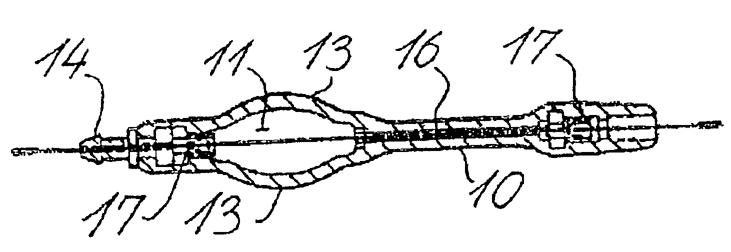
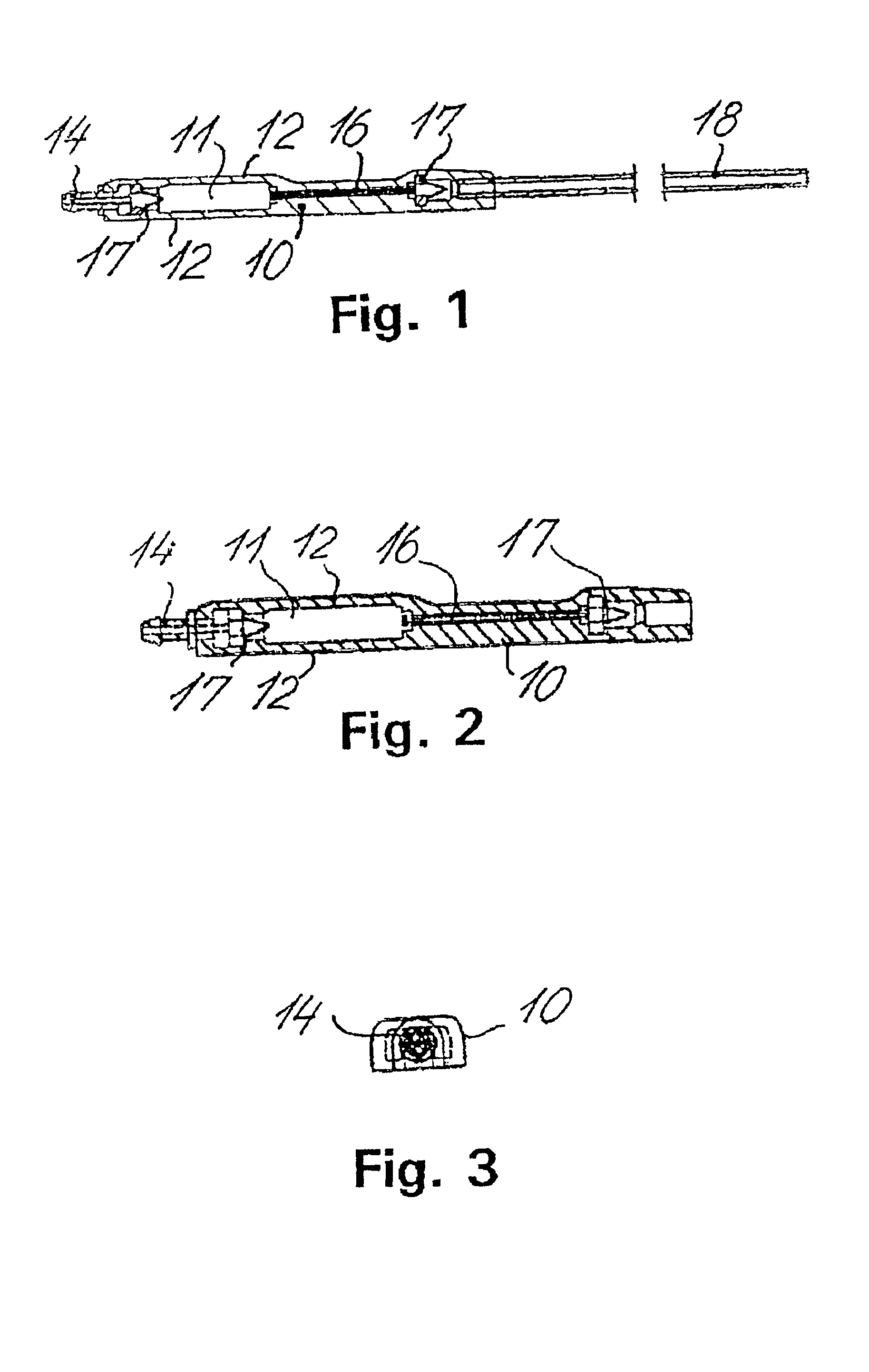
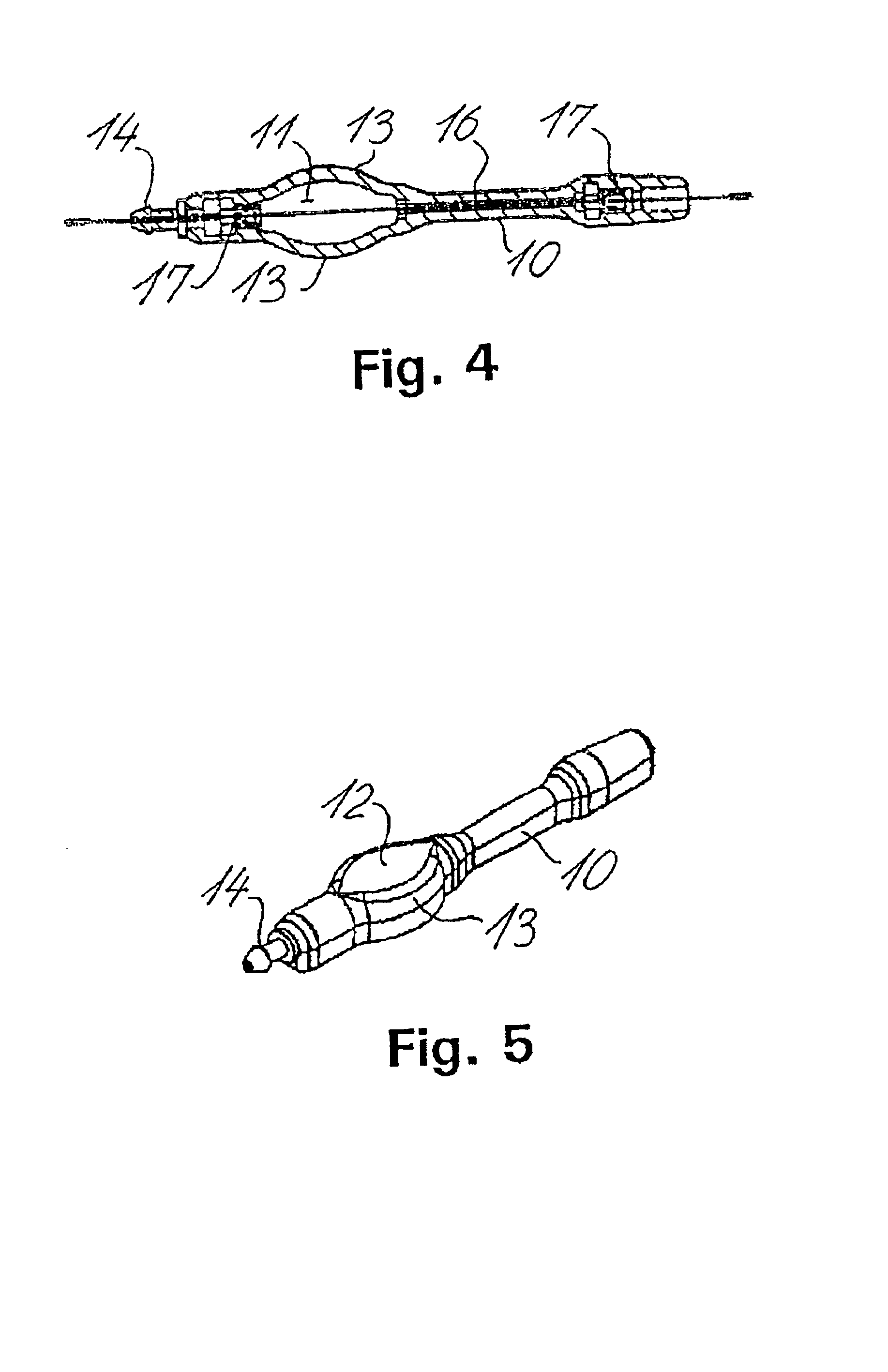
[0052]FIGS. 1-5 illustrate an embodiment of the cerebrospinal fluid shunt system according to the invention. The shunt system comprises a shunt body 10, which is made from a suitable material, such as a silicone rubber. An antechamber 11 may have opposite flat walls 12 made from hard silicone rubber, and opposite domed walls 13, which are made from soft, perforatable, self-healing silicone rubber. At the proximal end (the top end) the chamber walls end in a tip 14, to which a ventricular drain or catheter 15 can be connected and secured. At the distal end of the chamber 11 an inlet to a tubular flow restriction 16 is formed. A check valve or non-return valve 17 are arranged at the entrance to the antechamber 11 as well as at the outlet of the tubular flow restriction 16. Fluidic connection to the sinus sagittalis is provided by a tubular drain 18.

[0053]The ventricular drain 15 is attached to the tip or inlet connector 14, which is provided with an annular bead. The length of the con...


PUM


Abstract

A cerebrospinal fluid shunt system comprises a brain ventricle catheter (15) to insert into the brain ventricle (21) so as to drain cerebrospinal fluid from the brain ventricle, a sinus catheter (18) to insert into the sinus sagittalis system (22) for feeding the cerebrospinal fluid into the sinus sagittalis system, a shunt body member (10) connected at one end thereof to said brain ventricle catheter and at another end thereof to said sinus catheter system to provide fluidic communication between said brain ventricle catheter (15) and said sinus catheter (18), and a flow restriction (16) defined within the shunt body member (10) to maintain a resistance to fluid flow of the shunt system of less than 8 mm Hg/ml/min, such as 2-7 or 4-6 and preferably about 5 mm Hg/ml/min. When the shunt system is implanted the shunt body member (10) is placed subcutaneously on top of the calvarium of a patient, behind the coronal suture on one of side of the sagittal suture. One end of each of the catheters (15, 18) is then connected to a respective end of the shunt body member (10), and a second end of each catheter is inserted in the right ventricle (21) and in the sinus sagittalis system (22), respectively, via holes bored in the scull (19).

Description

[0001]This application claims the benefit of U.S. Provisional Application No. 60 / 231,578, filed Sep. 11, 2000 now abandoned.FIELD OF THE INVENTION[0002]The present invention relates to a cerebrospinal fluid shunt system for shunting cerebrospinal fluid from the brain ventricles to sinus sagittalis (including sinus transversus) in patients with so-called normal pressure hydrocephalus and in children with a combination of widely dilated ventricles and low intracranial pressure.BACKGROUND OF THE INVENTION[0003]Cerebrospinal fluid is formed in the ventricular system irrespective of the intracranial pressure (ICP). The formation rate is constant, with a range of 0.3-0.4 ml / min. (Børgesen and Gjerris 1987). Hydrocephalus, i.e. a pathological increase in the amount of intracranially located cerebrospinal fluid, arise when the outflow of the cerebrospinal fluid is obstructed, leading to an increase in the intracranial pressure and in the amount of intracranially located cerebrospinal fluid....

Claims


Application Information

Patent Timeline
IPC IPC(8): A61M27/00A61M1/00
CPCA61M27/006
Inventor BORGESEN, SVEND ERIK
Owner CSF DYNAMICS
Why Eureka
Try Eureka