
Manufacturing method for a carbon nanomaterial, a manufacturing apparatus for a carbon nanomaterial, and manufacturing facility for a carbon nanomaterial

a manufacturing apparatus and carbon nanotechnology, applied in the direction of polycrystalline material growth, crystal growth process, chemically reactive gas, etc., can solve the problems of difficult to fabricate monolayer nanotubes having comparatively uniform tube diameter and length, difficult to achieve stable mass production, and low yield. achieve the effect of high efficiency, efficient recovery of high-purity carbon nanomaterials

Inactive Publication Date: 2005-06-14
MITSUBISHI HEAVY IND LTD
View PDF3 Cites 46 Cited by
  • Summary
  • Abstract
  • Description
  • Claims
  • Application Information

AI Technical Summary

Benefits of technology

[0019]According to this type of carbon nanomaterial fabrication method, because a fluidized bed reactor is used, the compound (raw material) that includes carbon and the additive that includes a metal can be stably and continuously supplied and it is possible to uniformly mix and heat both. Thus it is possible to maintain a suitable temperature, pressure, and retention time and thereby to continuously deposit a high purity carbon nanomaterial.
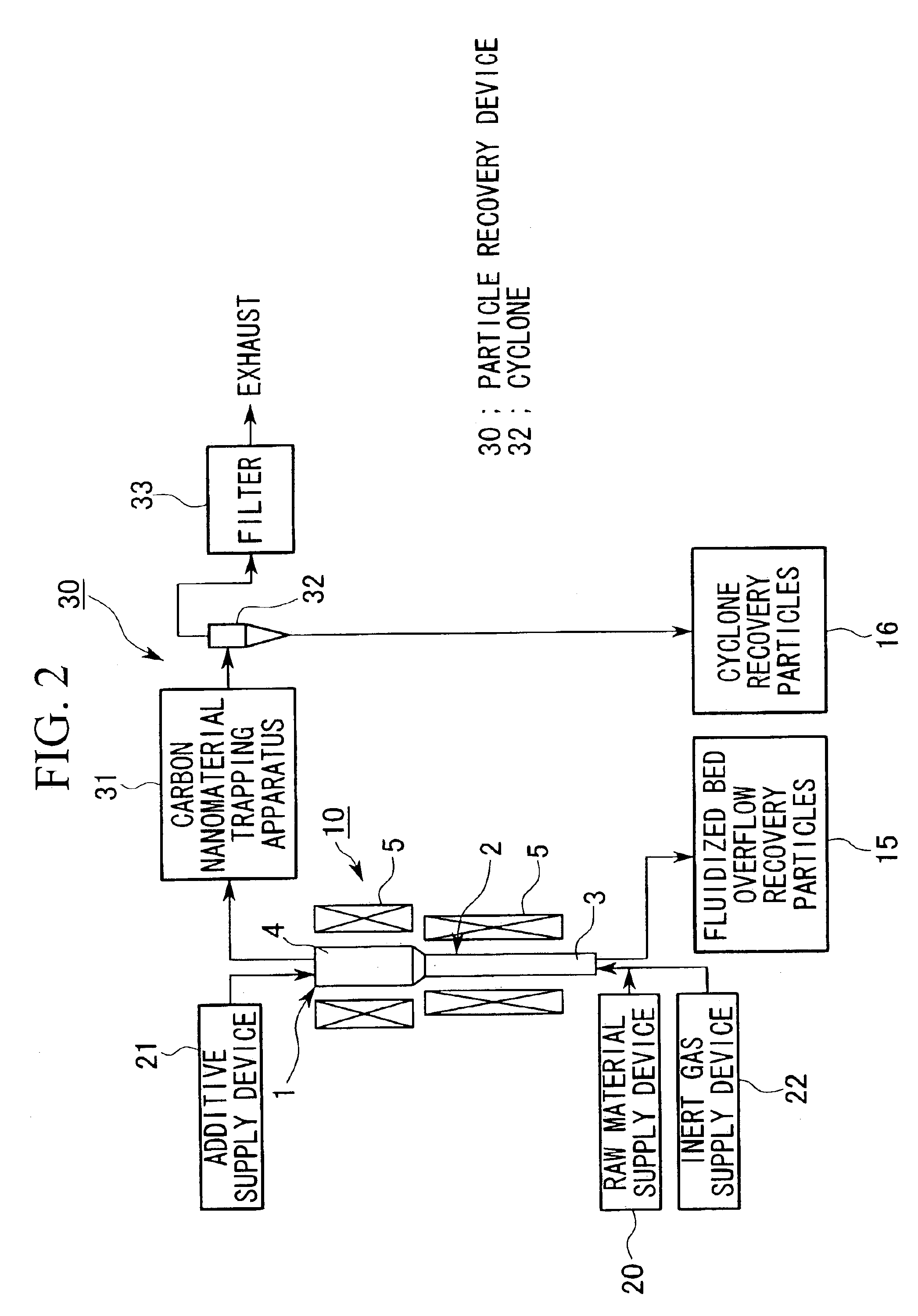
[0039]In the carbon nanomaterial fabrication facility described above, preferably at least one of a carbon nanomaterial trapping apparatus, a cyclone, or a filter is provided as the particle recovery device, and thereby the carbon nanomaterial can be reliably and efficiently recovered.

Problems solved by technology

However, in this method of fabrication, in addition to monolayer nanotubes, multilayer nanotubes, graphite, and amorphous carbon are mixed into the product, and not only is the yield low, but there is variation in both the tube diameter and length of the monolayer nanotubes, and it is difficult to fabricate monolayer nanotubes having comparatively uniform tube diameter and length at a high yield.
However, these fabrication methods are fabrication methods that are all at the experimental stage, and in particular, stable mass production is difficult because, for example, the yield of monolayer carbon nanotubes is low and continuous fabrication is not possible.

Method used


Image

  • Manufacturing method for a carbon nanomaterial, a manufacturing apparatus for a carbon nanomaterial, and manufacturing facility for a carbon nanomaterial
  • Manufacturing method for a carbon nanomaterial, a manufacturing apparatus for a carbon nanomaterial, and manufacturing facility for a carbon nanomaterial
  • Manufacturing method for a carbon nanomaterial, a manufacturing apparatus for a carbon nanomaterial, and manufacturing facility for a carbon nanomaterial

Examples


first embodiment

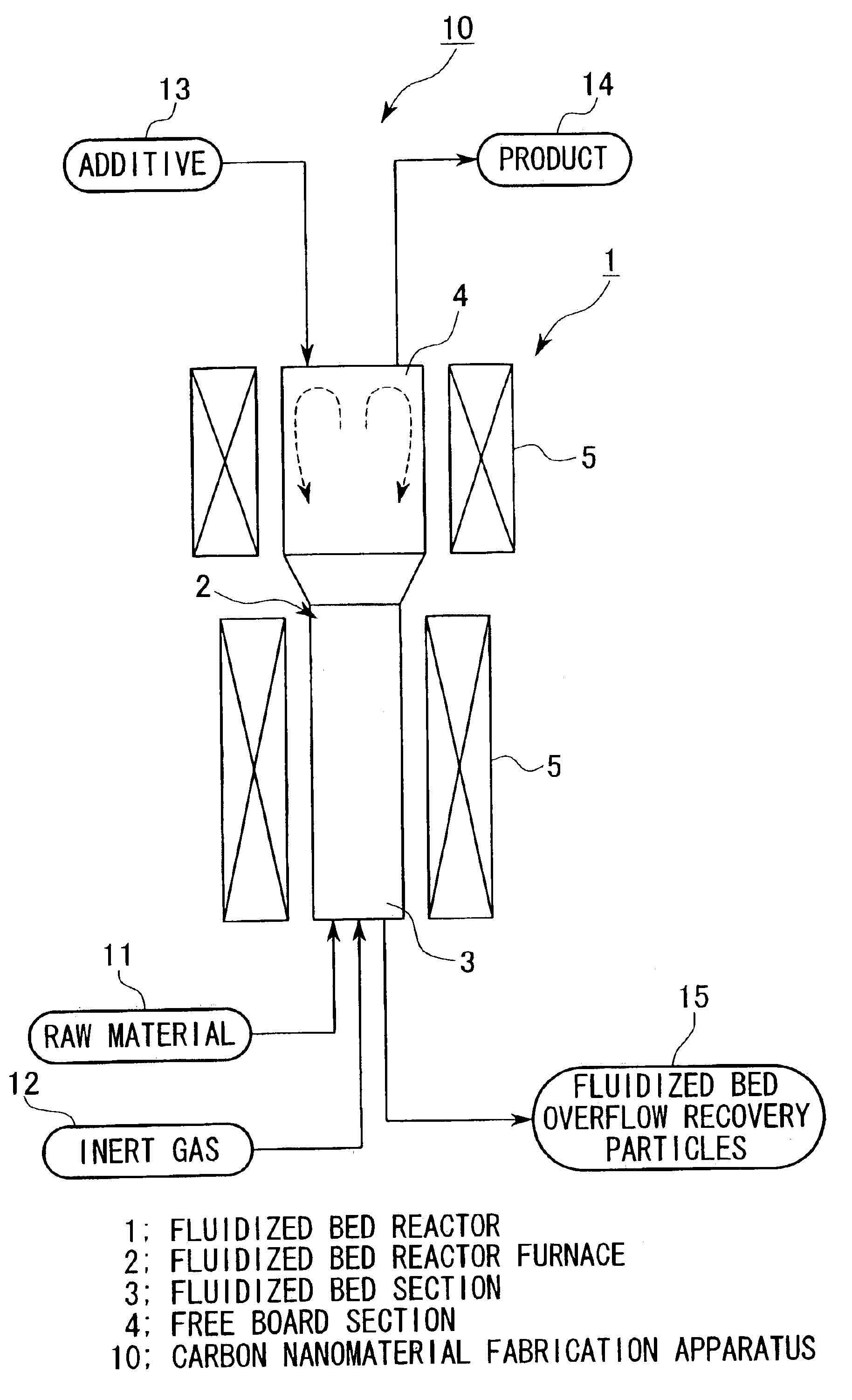
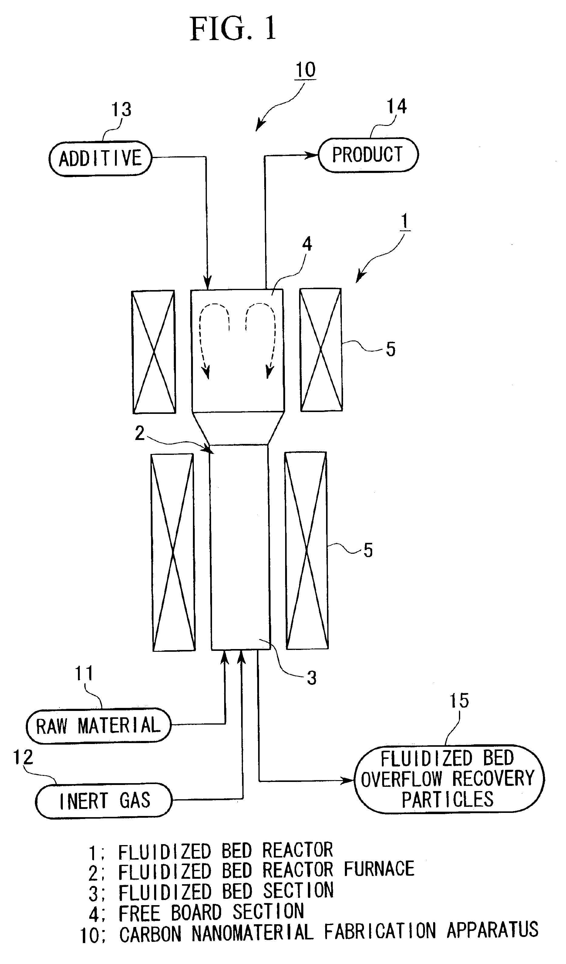
[0049]FIG. 1 is a structural diagram showing a carbon nanomaterial fabrication apparatus 10 that is the first embodiment of the present invention. Reference numeral 1 denotes a fluidized bed reactor, 2 denotes a fluidized bed reactor furnace, 3 denotes a fluidized bed section, 4 denotes a free board section, 5 denotes a heating device, and 10 denotes the carbon nanomaterial fabrication apparatus.

[0050]The fluidized bed reactor 1 is structured comprising free board section 4 that communicates with the upper part of the fluidized bed section 3, and providing a heating device 5 such as an electric heater or gas heater around the fluidized bed reactor furnace 2 comprising the fluidized bed section 3 and the free board section 4. Moreover, there is a bubbling fluidized bed and a turbulent fluidized bed in the fluidized bed reactor 2, and either one can be used.

[0051]The fluidized bed reactor furnace 2 uses, for example, a material that effects a chromizing process on a Ni alloy, and is a...

second embodiment

[0074]Next, as a second embodiment of the present invention, a carbon nanomaterial fabrication facility using the carbon nanomaterial fabrication apparatus and the fabrication method described above will be explained with reference to FIG. 2. Moreover, parts identical to those of the carbon nanomaterial fabrication apparatus shown in FIG. 1 are denoted by identical reference numbers.

[0075]This fabrication facility comprises the carbon nanomaterial fabrication apparatus 10 described above, a raw material supply device 20 that continuously and stably supplies at a predetermined amount a compound that includes carbon to the carbon nanomaterial fabrication apparatus 10, an additive supply device 21 that continuously and stably supplies at a predetermined amount an additive that includes a metal to the carbon nanomaterial fabrication apparatus 10, a gas supply device 22 that continuously supplies at a predetermined amount an inert gas to the carbon nanomaterial fabrication apparatus 10, ...

third embodiment

[0084]Finally, as a third embodiment of the present invention, a carbon nanomaterial fabrication facility using the carbon nanomaterial fabrication apparatus and the fabrication method described above, in particular, in the case that harmful chlorine constituents or the like are included in the product, will be explained with reference to FIG. 3. Moreover, parts identical to those of the carbon nanomaterial fabrication apparatus shown in FIG. 1 are denoted by identical reference numbers.

[0085]This fabrication facility comprises the carbon nanomaterial fabrication apparatus 10 described above, a raw material supply device 20 that continuously and stably supplies at a predetermined amount a compound that includes carbon to the carbon nanomaterial fabrication apparatus 10, an additive supply device 21 that continuously and stably supplies at a predetermined amount an additive that includes a metal to the carbon nanomaterial fabrication apparatus 10, a gas supply device 22 that continuo...


PUM


Abstract

The invention has as an object proving a carbon nanomaterial fabrication method that can continuously mass-produce a high purity carbon a nanomaterial. The tube-shaped or fiber-shaped carbon nanomaterial having carbon as the main constituent is fabricated with a compound that includes carbon (raw material) and an additive that includes a metal by using a fluidized bed reactor.

Description

BACKGROUND OF THE INVENTION[0001]1. Field of the Invention[0002]The present invention relates to a carbon nanomaterial manufacturing method in which a tube-shaped material or a fiber-shaped material having carbon as a main constituent is fabricated, a carbon nanomaterial manufacturing apparatus, and a carbon nanomaterial manufacturing facility.[0003]2. Description of the Related Art[0004]In recent years, tube-shaped or fiber-shaped carbon nanomaterials having carbon as the main constituent have become the focus of attention. What have been termed carbon nanotubes and carbon nanofibers are known as examples of this type of carbon nanomaterial.[0005]Among these, carbon nanotubes are tube-shaped carbon polyhedrons having a structure in which graphite sheets are closed into a cylindrical shape. These carbon nanotubes include multilayer nanotubes that have a multilayer structure in which graphite sheets are closed into a cylindrical shape, and monolayer nanotubes that have a monolayer st...

Claims


Application Information

Patent Timeline
IPC IPC(8): B01J8/18C01B31/00C01B31/02D01F9/127D01F9/12B82B3/00
CPCB01J8/18B82Y40/00C01B31/0233D01F9/127B82Y30/00B01J2208/00407B01J2208/00415B01J2219/00268Y10S977/842C01B2202/36C01B32/162C01B32/05B82B3/00
Inventor SETOGUCHI, TOSHIHIKOFUJIOKA, YUICHITSUCHIYAMA, YOSHIHIKOYASUTAKE, AKINORINODA, MATSUHEIKOBAYASHI, NORIHISANISHIDA, RYOICHINISHINO, HITOSHIOKIMI, KATSUHIDEHACHIYA, AKIHIRO
Owner MITSUBISHI HEAVY IND LTD
Learn More