System and device for characterizing shape memory alloy wires

Inactive Publication Date: 2005-07-12
UNIV OF KENTUCKY RES FOUND
View PDF19 Cites 34 Cited by
  • Summary
  • Abstract
  • Description
  • Claims
  • Application Information

AI Technical Summary

Benefits of technology

[0009]The biasing spring and the shape memory alloy are disposed on opposed sides of the movable mass in such a fashion that a force applied to the movable mass thereby is applied substantially through a center of stiffness of the movable mass. This feature advantageously prevents movement of the movable mass which may increase roll, pitch, or yaw error rotations thereof The displacement detector preferably measures a displacement of the movable mass in a colinear direction with a direction of movement of the movable mass and with a direction of the force applied is by the biasing spring and the shape memory alloy. This results in minimizing Abbe error, further improving the accuracy and sensitivity of the device. The shape memory alloy (SMA) selected may be any substance having the desired pro

Problems solved by technology

During the lifespan of the SMA actuator, loss of actuation can oc

Method used


Image

  • System and device for characterizing shape memory alloy wires
  • System and device for characterizing shape memory alloy wires
  • System and device for characterizing shape memory alloy wires

Examples


example 1

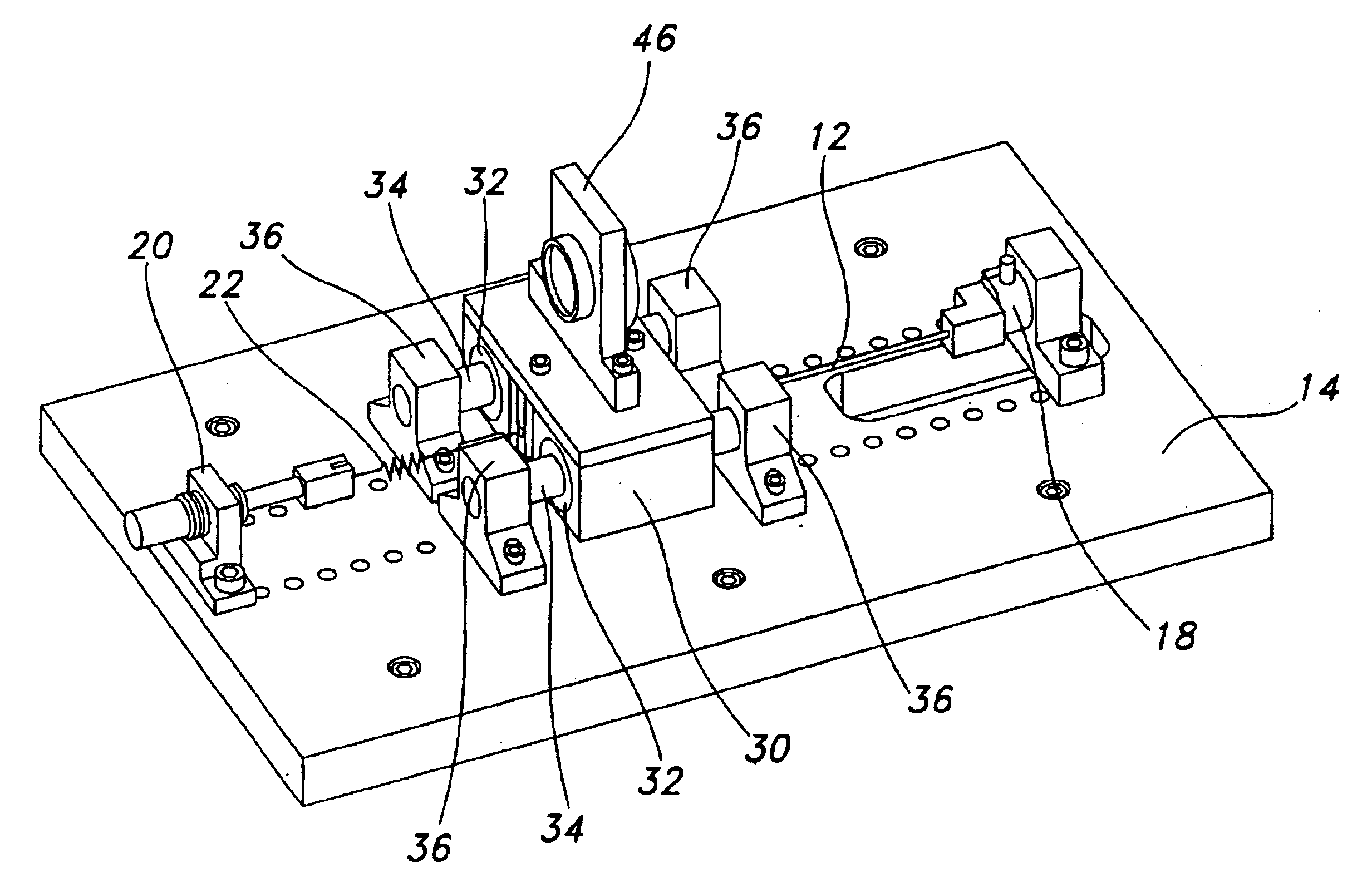
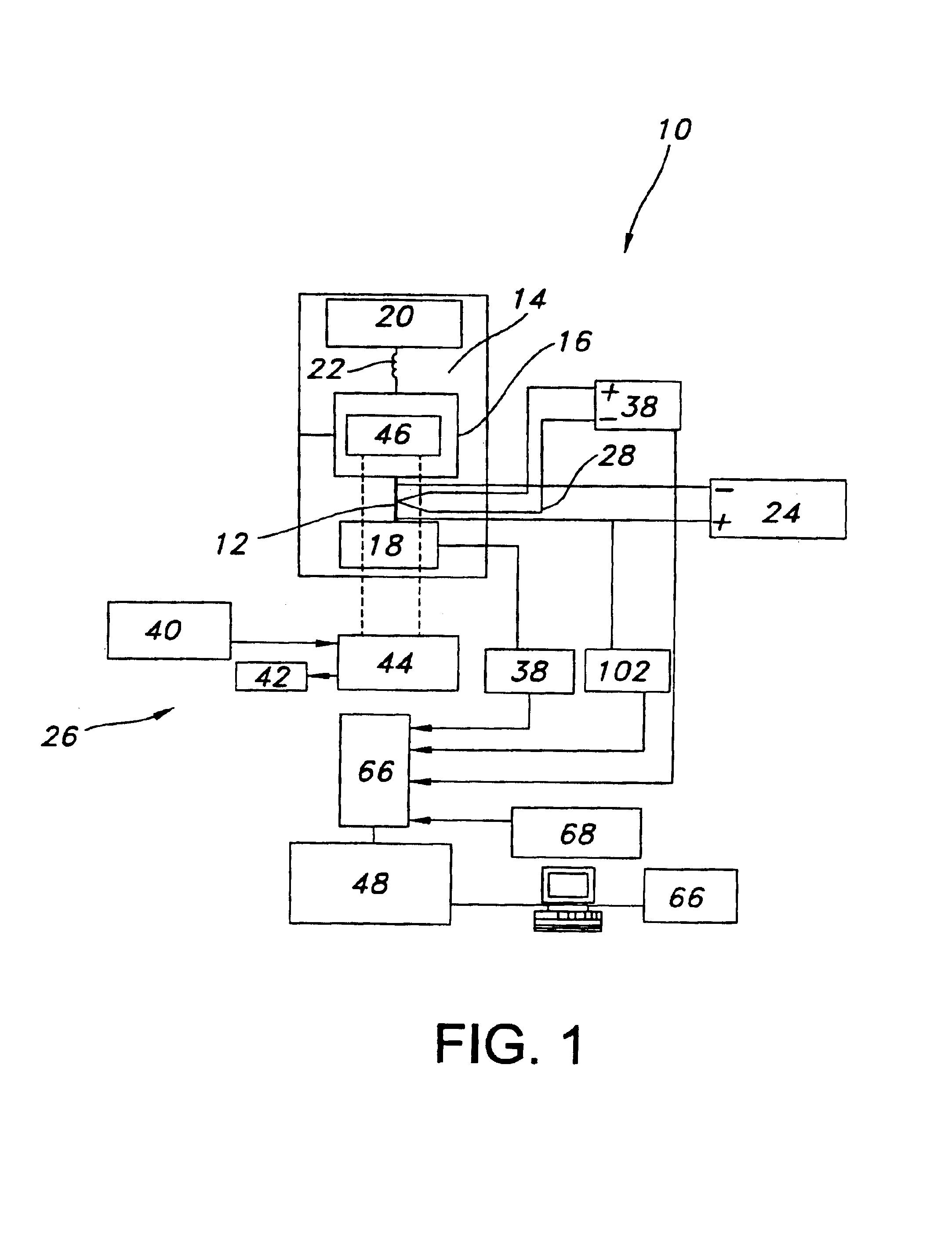
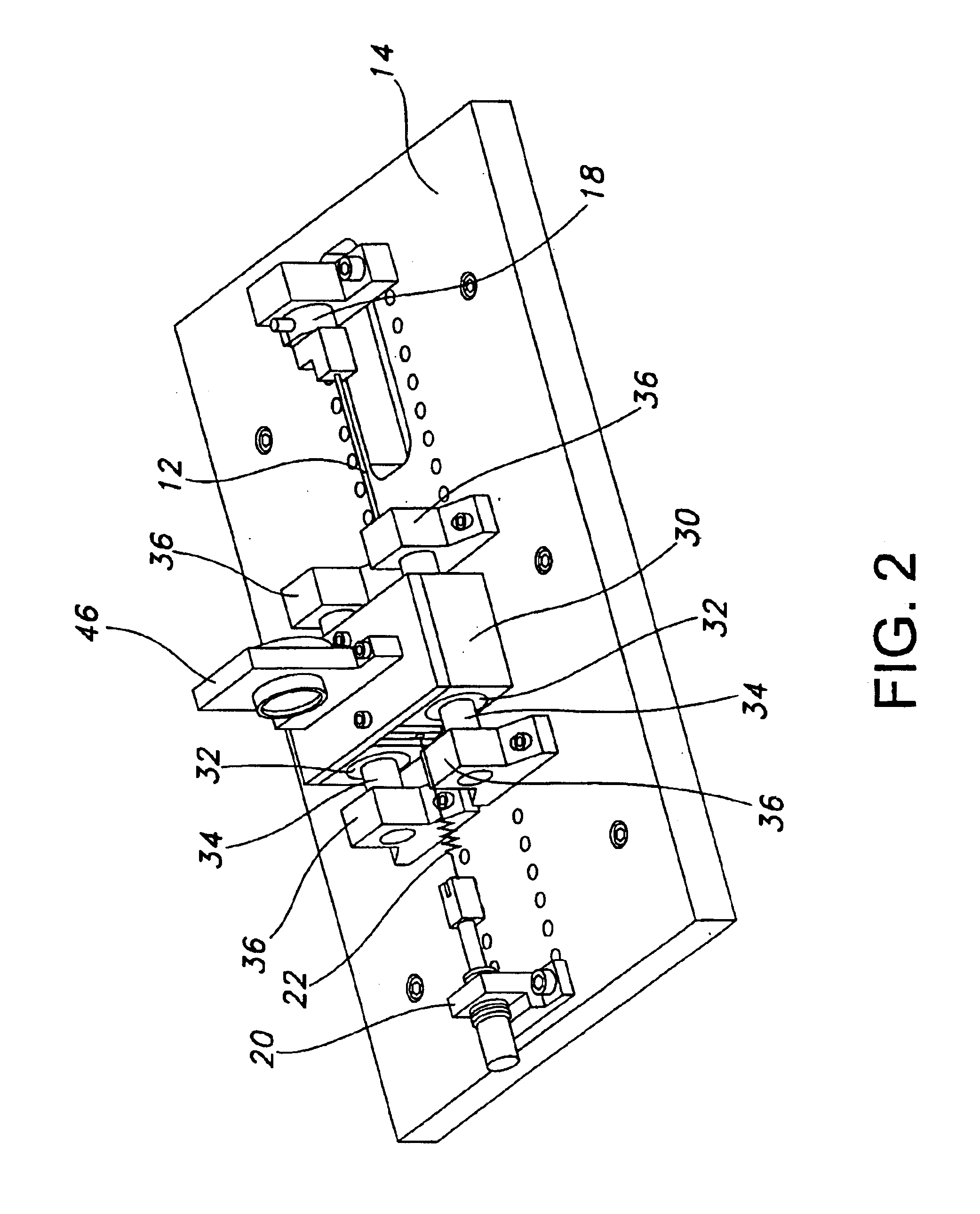
[0036]An instrument 10 for measuring a property of a shape memory alloy wire 12 is shown schematically in FIG. 1. The instrument 10 includes a base plate 14, a non-contact movable mass 16, a force gauge 18, an actuator 20, and a biasing spring 22 operatively connecting the movable mass 16 and the actuator 20. SMA wire 12 is attached between the movable mass 16 and the force gauge 18. Actuator 20 is a micrometer, and extending or retracting the micrometer adjusts the preload force on the SMA wire 12 via biasing spring 22. Force gauge 18 is a load cell capable of measuring the force generated by the SMA wire 12 during actuation. Actuation of the SMA wire 12 is initiated by supplying a voltage from s power supply 24. The current being supplied will vary on the diameter of the SMA wire 12 being tested. Required currents in accordance with various SMA wire diameters may be obtained from the manufacturers.

[0037]The position of the movable mass 16 caused by SMA wire 12 actuation is measure...

example 2

[0044]FLEXINOL wire having a diameter of 38.1 μm, 50.8 μm, 101.6 μm, and 152.4 μm (Dynalloy Inc, Costa Mesa, Calif.) was tested using the instrument described in Example 1. The material composition is 55.3% Ni by weight, Ti (Balance) and impurities less than 0.03%. The actuation temperatures of the material under 100 MPa load are recovery / contraction temperature of 70° C. ±15° C. and extension / cooling temperature of 50° C. ±15° C.

[0045]A pre-crimped SMA wire 12 was attached between the force gauge 18 and one end of the linear motion stage 30 using non-metallic screws and washers. A biasing spring 22 was connected between the other end of the linear motion stage 30 and the actuator 20. The preload force was calculated based on the preload stress in the wire (Table 1).

[0046]

TABLE 1Preload and Actuation StressActuation stress, Pa1 × 108Preload stress, Pa7 × 107

[0047]Nominal preload forces for different wire 12 diameters are provided in Table 2.

[0048]

TABLE 2Preload Forces for Different ...

example 3

[0056]The instrument 10 described in Example 1 was used to evaluate the effect of multiple actuation cycles of a SMA wire 12. The wire 12 was attached to the instrument as described in Examples 1 and 2. Desired voltage, current, number of actuation cycles, time of supply of current, and cooling time were input using controller 68. Variation in force and displacement were recorded by the data acquisition system 48, using the calculations described in Example 2. As shown in FIGS. 9a and 9b, the instrument recorded the variation in steady state force and displacement over 100 actuation cycles. It was shown that steady state force and displacement decrease with increasing number of actuation cycles, illustrating mechanical fatigue of the SMA wire 12 over time.


PUM


Abstract

Instruments and methods for measuring a property of a shape memory alloy are provided. The instrument includes a base plate, a non-contact movable mass, a force gauge, an actuator, a biasing spring, a heater for heating the shape memory alloy, and a non-contact displacement detector. The biasing spring and the shape memory alloy are disposed whereby a force applied thereby is applied substantially through a center of stiffness of the movable mass. The displacement detector measures a displacement of the movable mass in a colinear direction with a direction of movement of the movable mass and with a direction of the force applied by the biasing spring and the shape memory alloy. The linear motion stage comprises a housing and at least one guide bar, and wherein a calculated axial expansion of the guide bar is substantially equal to a calculated axial expansion of the base plate.

Description

[0001]This application claims the benefit of U.S. Provisional Patent Application Ser. No. 60 / 451,802, filed Mar. 4, 2003.TECHNICAL FIELD[0002]The present invention relates to applications making use of shape memory alloy (SMA), and more specifically to methods and instruments for characterizing the properties of SMA subjected to repeated cycles of contraction and elongation.BACKGROUND OF THE INVENTION[0003]The term shape memory alloy (SMA) is applied to that group of metallic compounds that demonstrate the ability to return to some previously defined shape or size when subjected to appropriate thermal procedure. These materials can be plastically deformed at relatively low temperature, and upon exposure to higher temperature will return to their shape prior to deformation. The basic physics involved in the shape memory effect is a reversible martensitic transformation. Repeated heating and cooling of these alloys results in cyclic motion, which provides utility as thermal actuators....

Claims


Application Information

Patent Timeline
IPC IPC(8): G01N3/08G01N3/14G01N25/00G01N3/32G01N25/16G01N33/20
CPCG01N3/32G01N25/16G01N33/20G01N2203/0222G01N2203/0224G01N33/204
Inventor VALLANCE, ROBERT RYANWALCOTT, BRUCE L.LUMPP, JAMES E.CHIKKAMARANAHALLI, SUMANTHRAWASHDEH, OSAMAH A.WOLSING, ERIC
Owner UNIV OF KENTUCKY RES FOUND
Why Eureka
Try Eureka