Hybrid DC-feed controller for a subscriber line interface circuit

a subscriber line interface and controller technology, applied in the field of hybrid dc-feed controllers for subscriber line interface circuits, can solve the problems of high cost of control circuitry on the high-voltage part, large power and area consumption, and increase the chip area and power of each additional dac, so as to reduce the overall chip area and power, increase the programmability of dc-feed control loops, and limit the number of amplifiers.

Active Publication Date: 2005-07-26
TEXAS INSTR INC
View PDF1 Cites 5 Cited by
  • Summary
  • Abstract
  • Description
  • Claims
  • Application Information

AI Technical Summary

Benefits of technology

[0007]An object of the present invention is to provide a hybrid, i.e. analog and digital, DC-feed control loop to put more functionality into the digital domain and to therefore reduce overall chip area and power. Another object of the present invention is to increase programmability of a DC-feed control loop. Another object is to limit the number of amplifiers in the transmit path of a DC-feed control loop and thereby reduce the low-frequency noise associated with the DC-feed path. A further object of the present invention is to provide a hybrid architecture for a DC-feed loop that is more versatile than prior art arrangements, and can be programmed to work with: 1) either current-feed SLICs or voltage-f

Problems solved by technology

Furthermore, the inclusion of control circuitry on the high-voltage part was expensive.
Thus, each programmable feature requires an additional DAC, adding integrated circuit chip area and power consumpti

Method used


Image

  • Hybrid DC-feed controller for a subscriber line interface circuit
  • Hybrid DC-feed controller for a subscriber line interface circuit
  • Hybrid DC-feed controller for a subscriber line interface circuit

Examples


Embodiment Construction

[0013]The numerous innovative teachings of the present invention will be described with particular reference to the presently preferred exemplary embodiments. However, it should be understood that these embodiments provide only a few examples of the many advantageous uses and innovative teachings herein. In general, statements made in the specification of the present application do not necessarily delimit the invention, as set forth in different aspects in the various claims appended hereto. Moreover, some statements may apply to some inventive aspects, but not to others.

[0014]The general principles of operation of inventive SLIC DC-feed control loop embodiments described herein will now be described, followed by a detailed description of specific embodiments and their principles of operation.

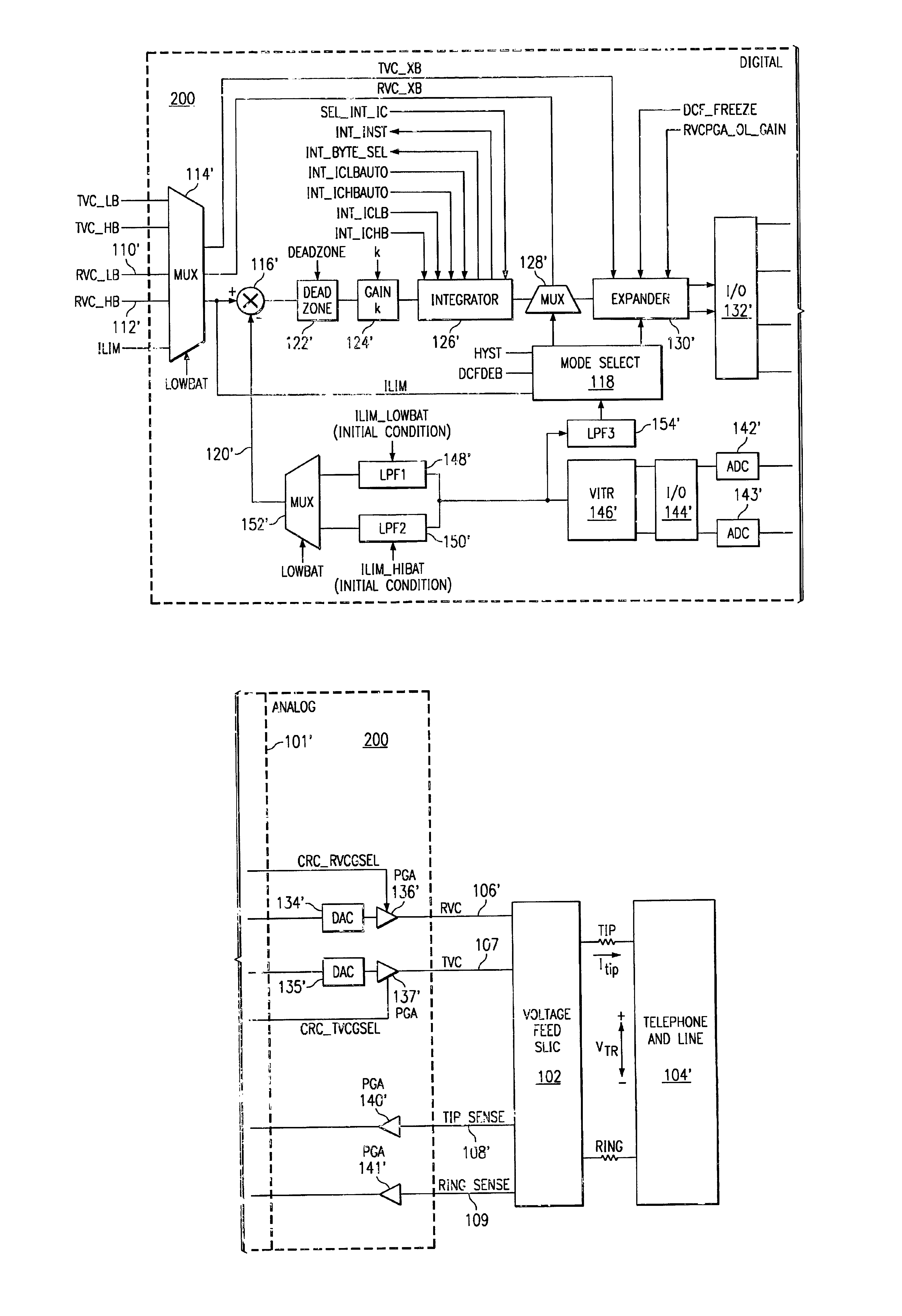
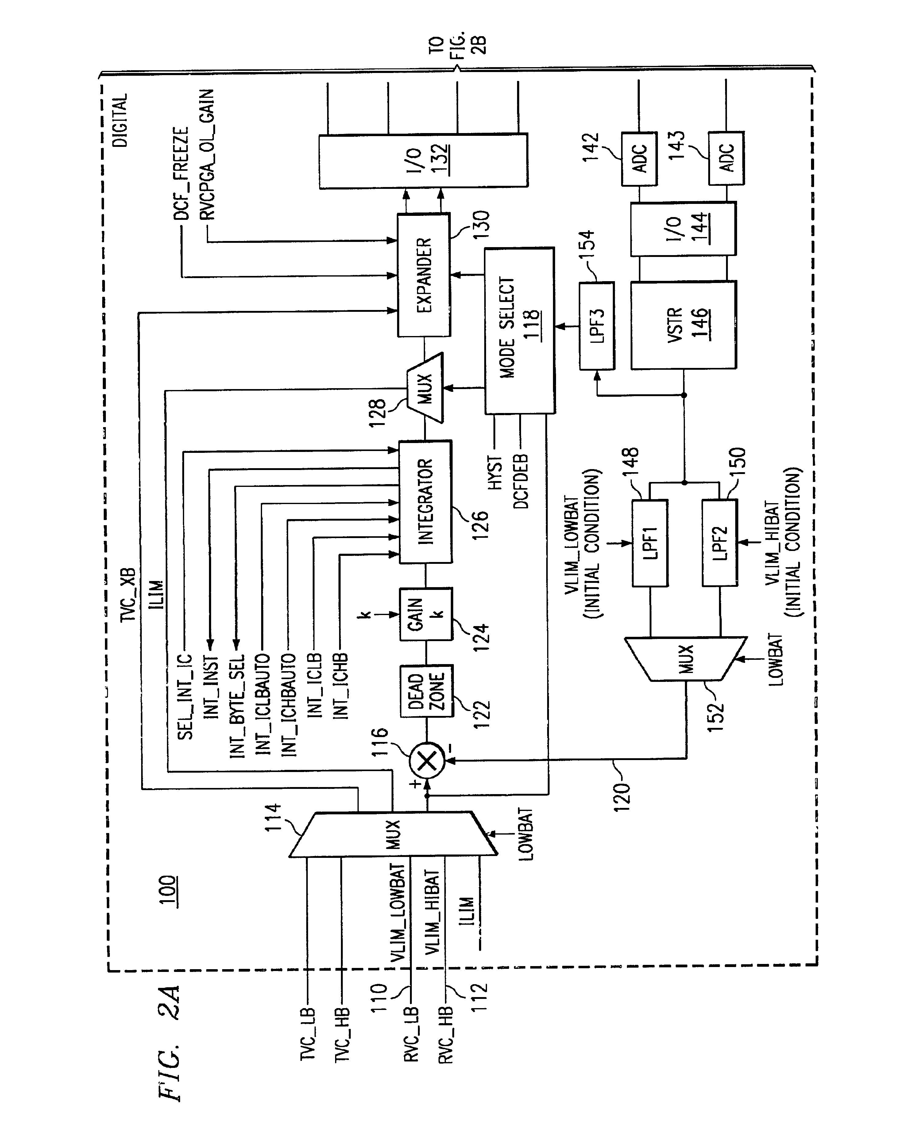
[0015]The inventive SLIC DC-feed control loop implementations described herein are provided in two modes, a current-feed mode and a voltage-feed mode, depending on the feed type of SLIC. For cu...


PUM


Abstract

A method and apparatus in a DC-feed controller for controlling a subscriber line interface circuit controlling voltage (alternately, current) on a telephone line comprising a pair of wires. A digital feedback signal is subtracted from a predetermined voltage (alternately, current) limit digital value to provide a digital error signal that represents the difference between the voltage (alternately, current) limit digital value and the digital feedback signal. The digital error signal is multiplied by a predetermined digital gain value to provide a scaled digital error value. The scaled digital error value is integrated over time to generate an integrated digital error signal having a first predetermined number n of significant bits. A modified digital error signal is received, comprising a second predetermined number m of bits, where m<n, of the integrated digital error signal as an input and an output an analog error signal is provided that is representative of the modified digital error signal and that comprises the control voltage. A sense signal is received, the sense signal representing a sensed voltage (alternately, current) on the telephone line, and is converted to a digital sense signal that is a representation of the sense signal. Finally, the digital sense signal is digitally low pass filtered to provide the digital feedback signal.

Description

TECHNICAL FIELD OF THE INVENTION[0001]This invention relates to telephone line interface circuits, and more particularly relates to current and voltage control in DC-feed control loops.BACKGROUND OF THE INVENTION[0002]The Plain Old Telephone System (“POTS”) consists of a network of local concentrations of telephone equipment, known as Central Offices (“CO”), which connect to surrounding subscribers. A subscriber's telephone is usually connected to the CO by way of two copper wires, which are referred to as the tip lead and the ring lead, in a familiar configuration commonly known as a twisted pair. FIG. 1 shows a high-level block diagram of a CO 10 and a subscriber 20.[0003]The two-wire interface at the CO is a high voltage interface and requires high voltage circuits to drive it. Circuitry in a modem day CO 10, such as shown in FIG. 1, typically includes a software driven micro-controller 12, or, alternatively, an ASIC, interfaced with a computer 11, a low-voltage mixed-signal Inte...

Claims


Application Information

Patent Timeline
IPC IPC(8): H04M1/738
CPCH04M1/738
Inventor BETTY, CHRISTOPHER L.RICHARDSON, DONALD C.
Owner TEXAS INSTR INC
Why Eureka
Try Eureka