
Composite foam structures

a foam structure and composite technology, applied in the field of composite rigid foam structure fabrication, can solve the problems of difficult skinning of foam with pore densities less than 20 to 30 ppi, and the inability to completely seal the surface, so as to eliminate the need for complex and costly machining, increase the weight of skinned foam, and improve the effect of skinning

Inactive Publication Date: 2005-08-16
ULSTREETCARET
View PDF24 Cites 32 Cited by
  • Summary
  • Abstract
  • Description
  • Claims
  • Application Information

AI Technical Summary

Benefits of technology

[0014]Plasma spraying appears to be the most common form of the thermal spraying operations. In a plasma spraying process, an inert gas is passed through an electric arc, thus creating an extremely hot ionized gas. The desired coating material, in powder form, is injected into the hot ionized gas stream. In the gas stream at least a substantial portion of the powdered coating material becomes partially molten or plastic. In general, the particles are not fully melted. The fluid particles are quenched and bonded when they strike the surface of the substrate. The inert gas is delivered under pressure to the electric arc so that it picks up the molten or plastic coating material and accelerates it onto the surface of the substrate. At the substrate surface a layer-by-layer buildup takes place through interparticle bonding and sintering reactions as the spray nozzle is rastered back and forth over the surface. The nature of the deposit is such that it is particularly effective in closing out surface porosity without penetrating very far into the body of the rigid foam. Internal porosity (closed cell) is frequently produced in coatings that are produced by thermal spray operations. This internal porosity is generally beneficial in ceramic thermal barrier coatings where it reduces thermal stress and stresses associated with thermal expansion mismatch.
[0018]The skins or coatings, which are formed in situ according to the present invention, conform exactly to the surface of the rigid foam and, therefore, are bonded tightly, directly and uniformly across the entire skinned area of foam. Slight penetration of the coating into the substrate (1 to 5 pore diameters) is generally beneficial to bonding. The pores in the substrate are defined by their peripheries. In open celled foams the peripheries are defined by ligaments, and in closed cell foams the pores are defined by panes or panels. The requisite degree of completeness and uniformity of bonding could not be achieved by fabricating the skin separate from the foam and then joining the two through a bonding agent. The amount of bonding agent would generally have to be increased to accommodate possible mismatched areas, thereby increasing the weight of the structure. Also, the continuous formed in situ skins are often so thin that they could not be easily and reliably handled and applied if they were to be made separately from the foam. The uniform continuity of the skin, such as would be provided by a separately formed skin, is achieved according to the present invention by a thermally sprayed formed in situ skin. Even very thin formed in situ thermally sprayed skins (less than about 0.010 inches in thickness) which bridge between widely spaced ligaments, but do not penetrate at the most more than 2 or 3 cell diameters into the foam, are directly bonded to the foam, and uniformly continuous and unbroken. In addition to providing a good bond, the substantially full attachment to all of the pore peripheries provides very good thermal transfer from the foam to the skin.
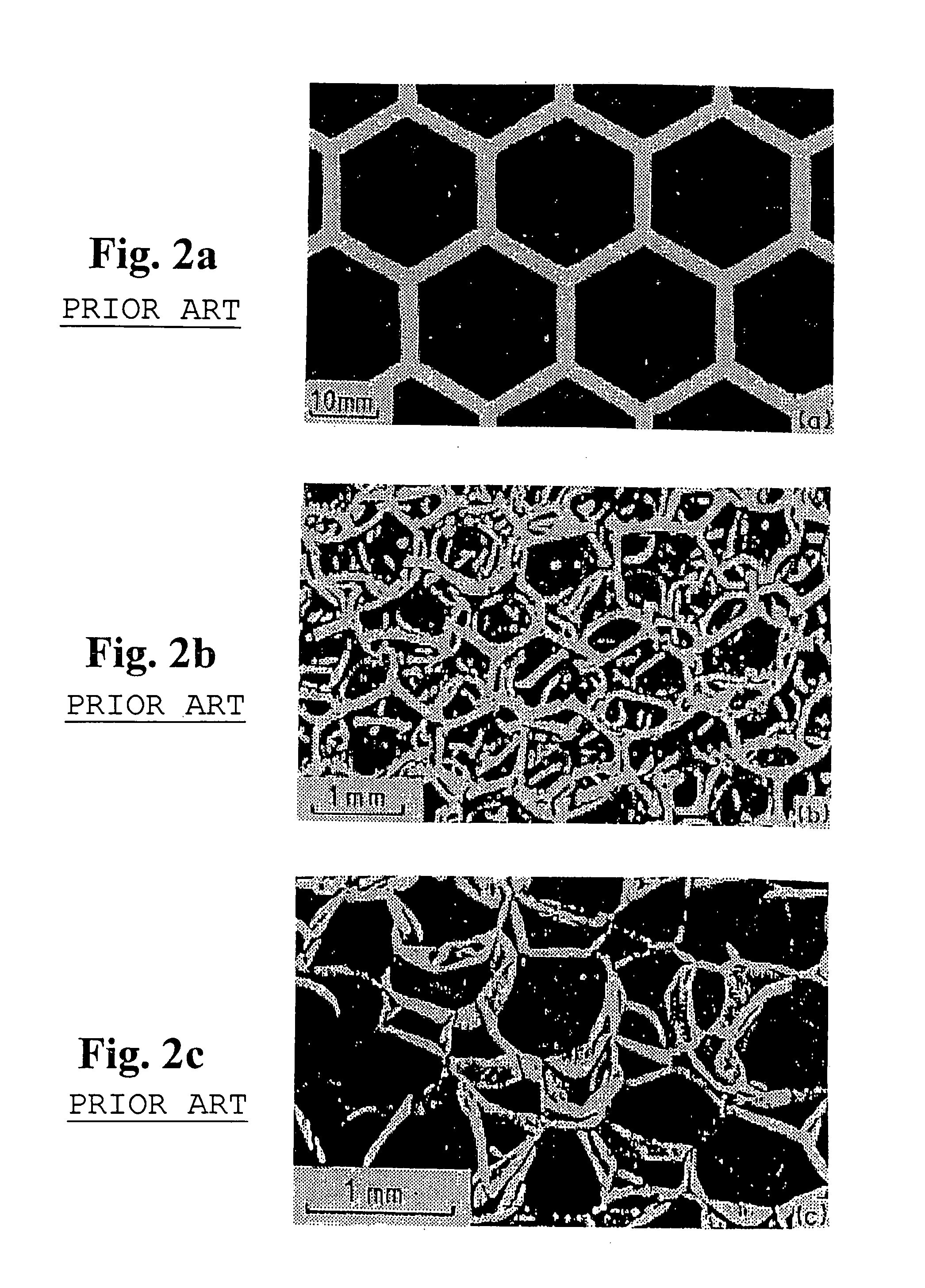
[0020]The cellular solid substrates to which the present invention is applicable include rigid open and closed celled materials, and materials which contain both in one body. The advantages of the present invention are particularly beneficial to reticulated structural foams where the penetration of the skin forming material into the open cells to any significant depth would impair the advantages of the foam. Reticulated structural foams are employed in many instances because of their light weight and porosity. Any skin forming process that results in substantially increasing the weight of the skinned foam or impairs the porosity subverts the reason for using the light weight foam. Thus, the ability to fully seal the face of a foam structure by bridging across and bonding to the foam with a very thin layer, without significantly penetrating the foam, provides very significant advantages. For actively cooled structures, the foam-faceplate (skin) composite eliminates the need for complex and costly machining and attachment of coolant manifolds, channels, and the like.

Problems solved by technology

If the pore size is too large, it may not be possible to completely seal the surface while also minimizing the weight of the skin.
Foam with pore densities of less than about 20 to 30 ppi is often impossible to skin unless other means are combined with the thermal spray processing.

Method used


Image

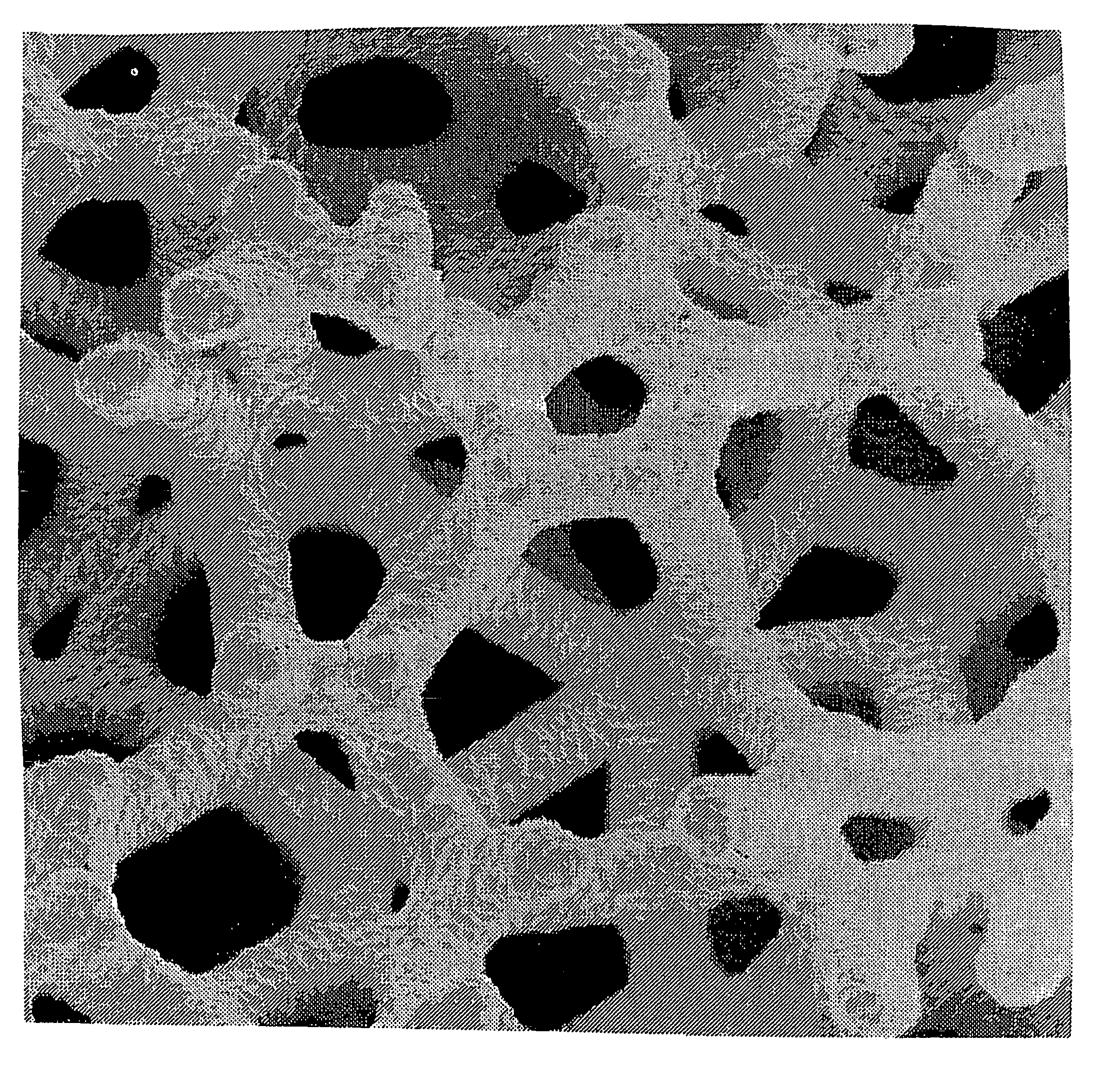
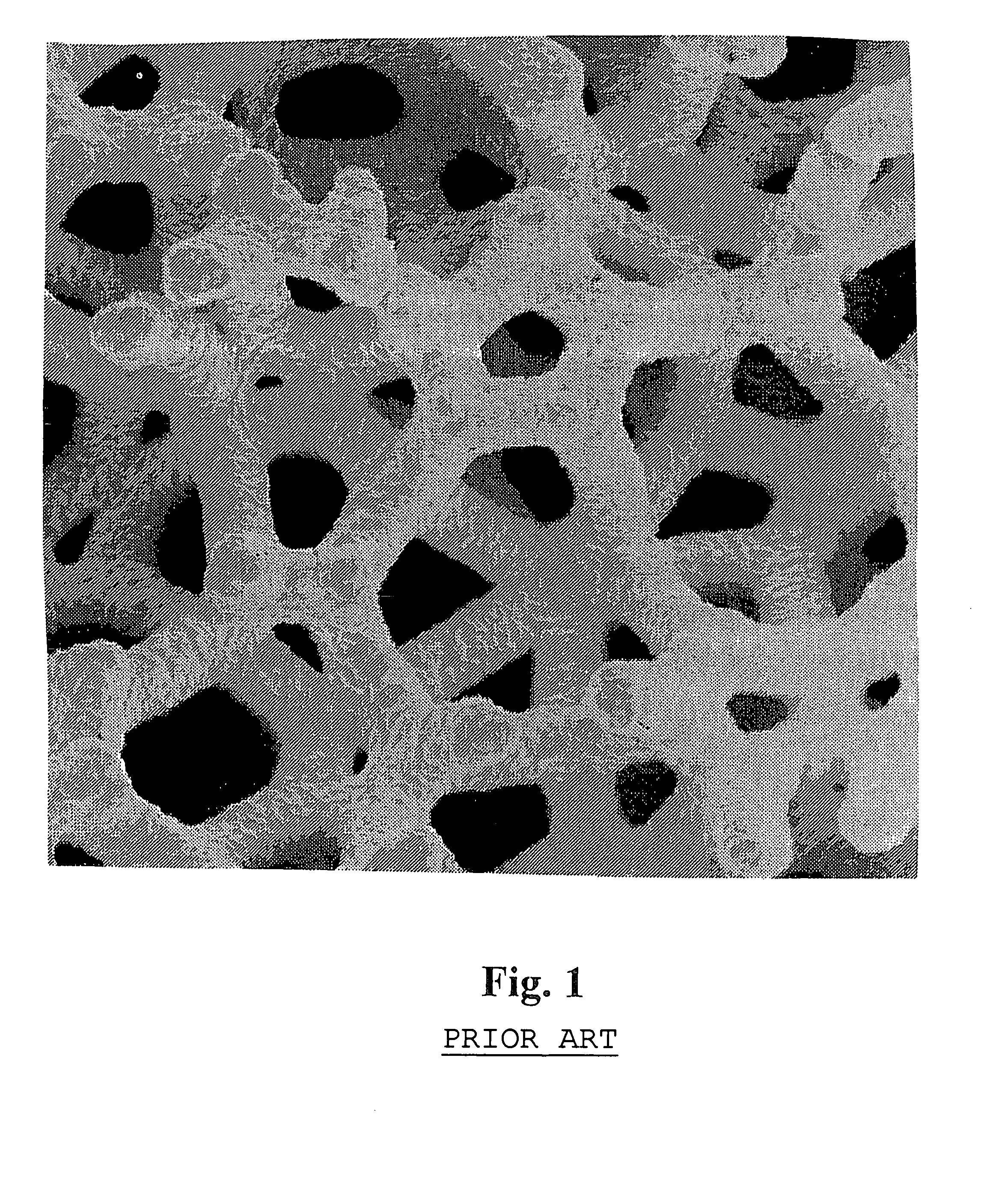
  • Composite foam structures
  • Composite foam structures
  • Composite foam structures

Examples


Embodiment Construction

[0028]In a preferred embodiment of the invention, which has been selected for purposes of illustration only and not limitation, a regeneratively cooled, liquid propellant rocket engine was fabricated. The porous material was used as a heat exchanger to cool the inner wall of the rocket. This structure consisted of an inner wall of rhenium, encased in a rhenium-carbon open-cell foam heat exchanger, which is skinned with an Inconel alloy shell by a thermal spray processing. The inner rhenium shell and the outer Inconel shell were leak free and capable of containing flowing hydrogen at 500 to 1000 pounds per square inch (psi). In the manufacture of this embodiment, a molybdenum mandrel was fabricated whose outer surface replicated the desired inner geometry of the rocket. The outer surface of the mandrel was then coated with rhenium by chemical vapor deposition procedures (CVD) to a thickness of 1.5–2.5 mm. A block of open-pore, vitreous carbon foam (20 mm×20 mm×30 mm) was then pressed...


PUM

PropertyMeasurementUnit
thicknessesaaaaaaaaaa
sizeaaaaaaaaaa

Abstract

A composite rigid foam structure that has a skin or coating on at least one of its surfaces. The skin is formed in situ by thermal spray techniques. The skin is bonded substantially throughout the surface of the porous substrate to the peripheries of the pores. The skin on the average does not penetrate the surface of the substrate by more than the depth of about 2 to 5 pores. Thus, thermal spraying the skin onto the rigid foam produces a composite that is tightly and uniformly bonded together without unduly increasing the weight of the composite structure. Both thermal conductivity and bonding are excellent.

Description

RELATED APPLICATIONS[0001]This application claims priority to provisional application No. 60 / 108,667, filed Nov. 16, 1998.STATEMENT REGARDING FEDERALLY SPONSORED RESEARCH OR DEVELOPMENT[0002]The U.S. Government has a paid-up license in this invention and the right in limited circumstances to require the patent owner to license others on reasonable terms as provided for by the terms of SBIR Phase II contract No. NAS3-27239 awarded by NASA Glenn Research Center, and Contract No. F33615-01-C-5215 awarded by Air Force.BACKGROUND OF THE INVENTION[0003]1. Field of the Invention[0004]This invention relates to the fabrication of composite rigid foam structures, and to the structures so fabricated. In particular, the structures are composed of a rigid foam material that has at least one face sealed or skinned with a thin skin that is tightly and uniformly adhered to but does not significantly penetrate the foam.[0005]2. Description of the Prior Art[0006]A cellular solid is made up of an inte...

Claims


Application Information

Patent Timeline
Patent Type & Authority Patents(United States)
IPC IPC(8): B32B15/02B32B18/00
CPCC04B41/5071C04B41/87C23C4/10C23C30/00C23C4/00Y10T428/12479Y10T428/249957
Inventor WILLIAMS, BRIAN E.BROCKMEYER, JERRYTUFFIAS, ROBERT H.
Owner ULSTREETCARET
Learn More