
Non-curling reinforced composite membranes with differing opposed faces, methods for producing and their use in varied applications

a technology of opposed face and reinforced composite membrane, which is applied in the direction of weaving, transportation and packaging, and other domestic objects, can solve the problems of limiting the usefulness of the material, affecting the performance of the material, so as to achieve the effect of optimizing performan

Inactive Publication Date: 2005-08-16
SAINT GOBAIN PERFORMANCE PLASTICS CORP
View PDF9 Cites 32 Cited by
  • Summary
  • Abstract
  • Description
  • Claims
  • Application Information

AI Technical Summary

Benefits of technology

The resulting composite exhibits minimal curling, allowing for easy handling and optimized performance in applications requiring distinct frictional and surface characteristics from each face, such as in material handling and surface protection.

Problems solved by technology

In the past, these attempts have yielded materials with a strong tendency to curl, making their handling extremely difficult and limiting their usefulness.
The curling tendency is due to imbalanced stresses generated in manufacturing these composites, the result of differences in the curing characteristics, thermal coefficients of expansion, and modulae of the two components.

Method used


Image

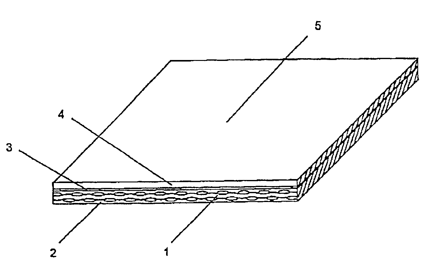
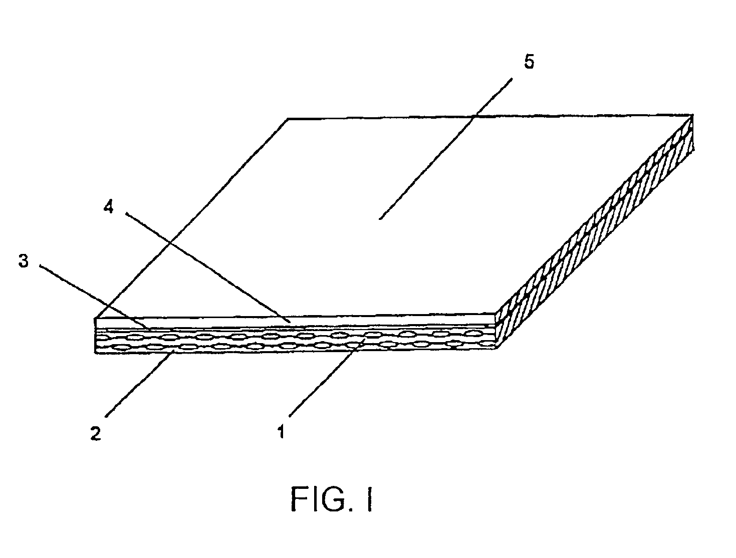
  • Non-curling reinforced composite membranes with differing opposed faces, methods for producing and their use in varied applications
  • Non-curling reinforced composite membranes with differing opposed faces, methods for producing and their use in varied applications

Examples


example 1

[0018]One face of a roll of commercially available PTFE / glass fabric (Chemfab Chemglas® Basic 5), containing style 2116 glass fabric as a reinforcement and comprised of about 50 percent by weight PTFE resin and 50 percent by weight glass, is rendered bondable by applying a mixture of colloidal silica dispersion (DuPont Ludox® 40), PFA fluoropolymer resin solution (Dupont TE-9946), surfactants, stabilizers, and water; wiping off the excess; drying; baking; and fusing. The fabric weighs about 5.4 ounces per square yard (osy) and is about 0.005 inches thick.

[0019]Using conventional PTFE tower-coating equipment, a coating of an LSR formulation composed of 50 parts by weight each of Wacker Silicones Elastosil® LR6289A and LR6289B and about 12 parts by weight of a red iron oxide masterbatch containing about 35 percent iron oxide and about 65 percent vinyl terminated silicone polymer, is applied to the bondable face of the Chemglas Basic 5. The tower is operated to provide conditions of ti...

example 2

[0021]One face of another roll of the PTFE / glass fabric used in the above example is rendered bondable by treatment with a solution of sodium, naphthalene, and glycol ether. It is coated using the procedure described in Example 1, yielding a composite with physical properties almost identical to those of Example 1.

example 3

[0022]One face of a length of Chemltas 64-40916, a Chemfab product comprised of Style number 64 glass fabric saturated / coated with 40 percent by weight PTFE, is rendered bondable by application of the colloidal silica formulation as described in Example 1 and coated with 8 osy. of silicone rubber. The resulting product is fabricated into a belt 50 meters long and 1.5 meters wide. It is substituted for a conventional glass-reinforced silicone rubber belt used as a conveyor and release surface in the assembly of plastic wine bags by heat sealing. The silicone release surface of the conventional belt performs to the user's satisfaction, but the construction is difficult to drive on the user's equipment due to excessive frictional force generated when the rubber non-working face of the belt, i.e., the face that does not contact the product, slides over stationary components of the machine. The PTFE non-working face of the example belt generates minimal frictional force against the machi...


PUM

PropertyMeasurementUnit
thicknessaaaaaaaaaa
thicknessaaaaaaaaaa
thicknessaaaaaaaaaa

Abstract

A double-faced PTFE-silicone rubber reinforced composite with curling tendency controlled is achieved by coating one side of a balanced PTFE / glass composite with liquid silicone rubber. Each face of the composite can perform independent functions in a single application, thereby optimizing performance.

Description

[0001]This application claims the benefit of U.S. Provisional Application No. 60 / 176,779, filed Jan. 19, 2000, under 35 U.S.C. §119(e).BACKGROUND OF THE INVENTION[0002]This invention relates to new and useful reinforced composite membranes for use in conveying, material handling, surface modifying, surface protection, and barrier applications, in which the two opposing faces of the membrane differ significantly in composition and physical characteristics, each face being constructed to perform independent functions in a given single application, thereby optimizing overall performance.[0003]More specifically, this invention relates to reinforced composite membranes in which one face is a perfluoropolymer, such as polytetrafluoroethylene (PTFE), and the other face is an elastomer. Although the use of elastomeric materials of varied compositions is contemplated, silicone rubber is the preferred elastomeric component.[0004]Polytetrafluoroethylene (PTFE) coated fiberglass fabrics and sil...

Claims


Application Information

Patent Timeline
Patent Type & Authority Patents(United States)
IPC IPC(8): B65G15/32B65G15/34C08J5/04C08J7/04C08J7/00D06N3/04D06N3/12D06N3/18D06N3/00B32B27/04B32B27/30B32B25/08
CPCB32B37/0015B65G15/34C08J5/04C08J5/043C08J7/047D06N3/047D06N3/128D06N3/18B32B2305/08B32B2319/00B32B2327/18B32B2433/02B65G2201/02C08J2327/18C08J2483/00D06N3/183D06N3/186Y10T442/2057Y10T442/2066Y10T442/2926Y10T442/232Y10T442/2992Y10T442/2098Y10T442/2361Y10T442/2041Y10T442/2369Y10T442/2311Y10T442/2344Y10T442/2402Y10T442/2049C08J7/0427
Inventor KEESE, FRANK M.
Owner SAINT GOBAIN PERFORMANCE PLASTICS CORP
Learn More