

Particle sizer and DNA sequencer
a particle sizer and dna sequencer technology, applied in the direction of fluid pressure measurement, liquid/fluent solid measurement, peptide measurement, etc., can solve the problems of inability to achieve optimal particle separation and insufficient solution flow, and achieve rapid separation, facilitate particle sizing, and high throughput
- Summary
- Abstract
- Description
- Claims
- Application Information
AI Technical Summary
Benefits of technology
Problems solved by technology
Method used
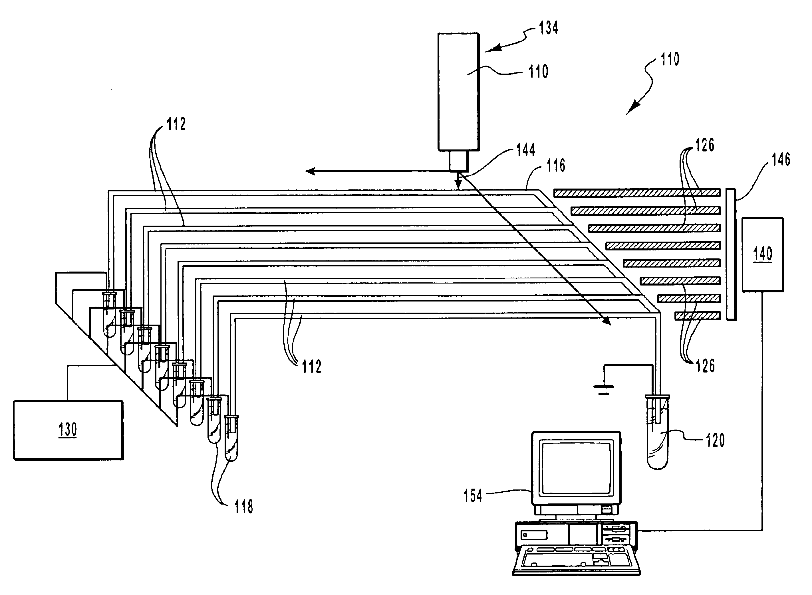
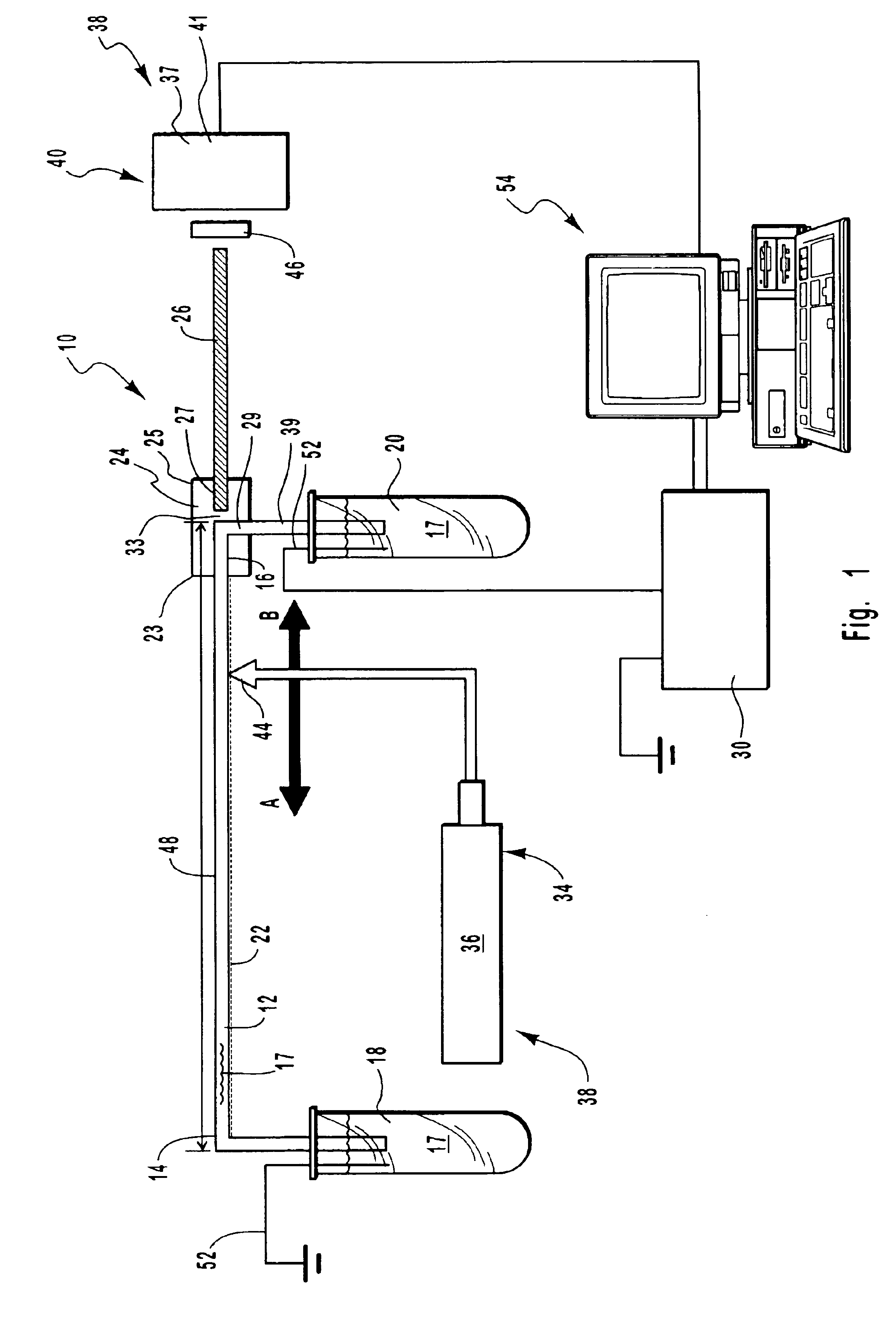
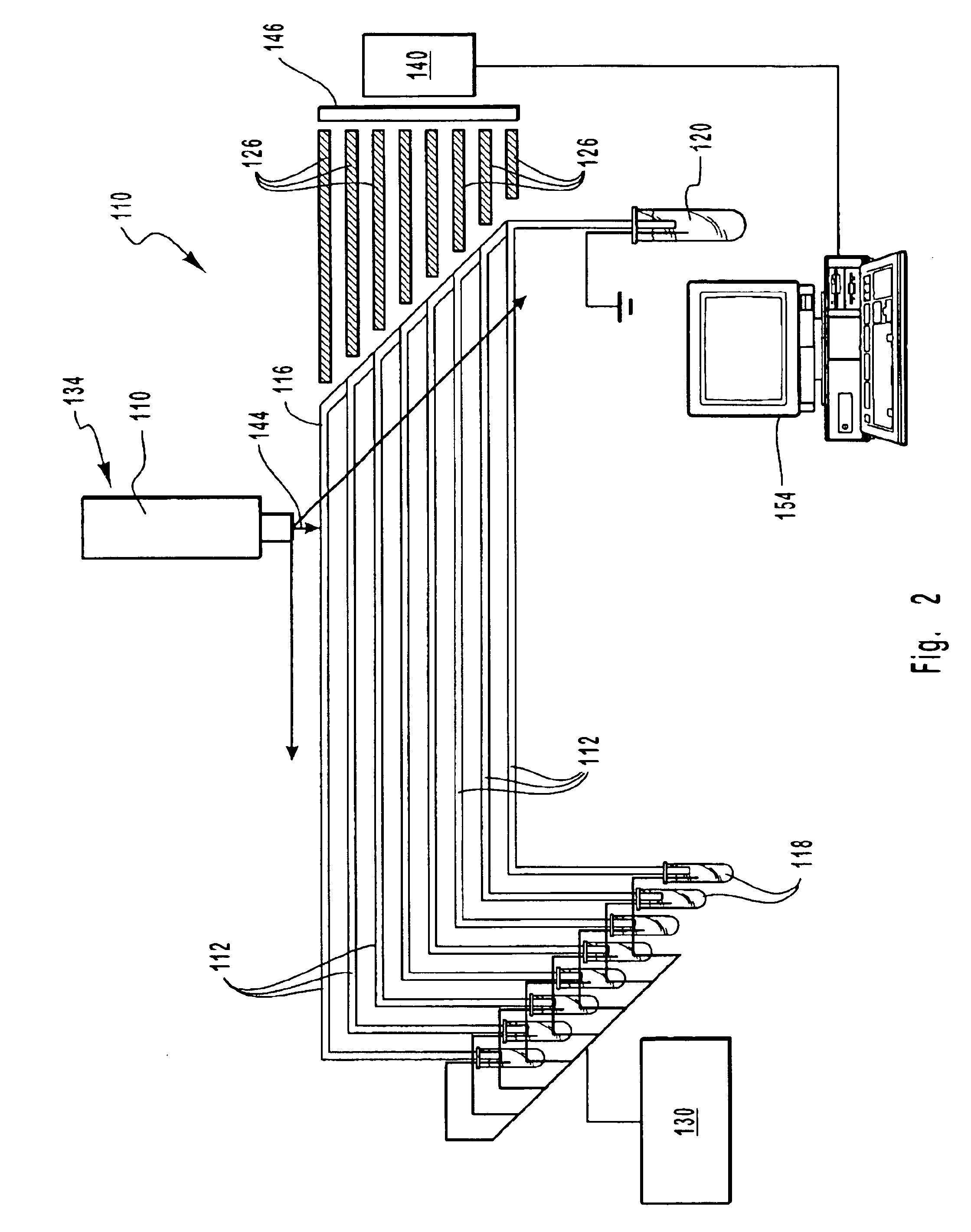
Image

Examples
example 1
[0061]Electrophoresis takes advantage of the differences in the movement of ions in an electrical field, in solution. The electrophoretic velocity (vep) for ions in a fluid with viscosity (η) and in an electrical field (E) varies according to the charge state (q) and ionic radius (r) of the ion according to the equation: vep=5 / 3qπ r ηE
[0062]Referring to FIG. 3, when practiced in a fused silica capillary 210, the electrophoresis process is also influenced by a bulk movement of the electrolyte fluid in the capillary 210. This movement is caused by the formation of an electrical double layer 214 at the walls 212 of the capillary 210. The cause of this double layer 214 is based on the existence of negative silanol charges 216 at the fused silica surface. These fixed silanol 216 charges attract positive charges 218 from the fluid. Overall there will also be an attraction of the positive charges 218 towards the cathode causing the bulk fluid movement called electroosm...
example 2
Separation of a DNA Ladder Using TBE Buffer
[0064]A sample of particles was loaded into a capillary electrophoretic device of the present invention. The capillary was filled with TBE buffer with a gel sieving material. The gel sieving material was present at a concentration between about 0.5% and about 1%. The separation was performed on a device with about a 25 cm capillary length. As seen in FIG. 4, the separation was excellent. The separation of FIG. 4 was performed in about 50 minutes. However separations can be achieved in less than 10 minutes using a 25 cm column but with decreased resolution at the large fragment end. Nevertheless separations of PCR products that achieve + / −5 base pair resolution at fragment lengths below 500 bp, in five minutes have been achieved.
example 3
Separation and Detection of a 1,500 bp DNA Ladder
[0065]A 1,500 bp DNA ladder was obtained and loaded into a standard capillary electrophoretic device with a stationary detection beam. A current was applied across the capillary. The particles were detected as they moved past the detection window of the device. As seen in FIG. 5, the separation and detection of the 1,500 bp DNA ladder took about 1,400 seconds or over 23 minutes.
[0066]A 1,500 bp DNA ladder was also loaded into the capillary electrophoretic device of the present invention. After a period of about 13 minutes, the migration of the particles was terminated by disconnecting the voltage. The detection beam was moved along the length of the capillary to image the complete electrophoretic separation of the particles. In this manner, each separated fragment does not have to pass by a detection window, but the complete separation channel becomes the detection window. The detection process took only about 10 seconds longer of add...
PUM
| Property | Measurement | Unit |
|---|---|---|
| refractive index number | aaaaa | aaaaa |
| refractive index number | aaaaa | aaaaa |
| power | aaaaa | aaaaa |
Abstract
Description
Claims
Application Information