Gas turbine control system

a control system and gas turbine technology, applied in the direction of control systems, electric generators, testing/monitoring, etc., can solve the problems of unstable power plant operation under high-load conditions, undesirable situations, and so as to prevent excessive high or low temperature of combustion gas and loss of flame, the effect of preventing loss of flame and avoiding loss of flame of gas turbin

Inactive Publication Date: 2005-09-20
KK TOSHIBA
View PDF4 Cites 35 Cited by
  • Summary
  • Abstract
  • Description
  • Claims
  • Application Information

AI Technical Summary

Benefits of technology

[0053]According to this aspect of the invention, since the speed control means has a limiter means, it is possible to limit temporary variations of the combustion gas flow rate, thus preventing excessively high or low temperature of the combustion gas and loss of flame in the gas turbine.
[0054]According to a further aspect of the invention, there is provided a gas turbine control system for controlling a gas turbine unit including an air compressor for producing compressed air, the compressor having inlet guide vanes or blades for adjusting an air flow rate into the compressor, a combustor for combusting a fuel mixed with the compressed air from the compressor to produce a combustion gas, a gas turbine receiving the combustion gas from the combustor and driven by the combustion gas to drive the compressor and an electric generator driven by the gas turbine unit and connected to an electric power system: the gas turbine control system comprising: inlet guide blade control means that controls the inlet guide vanes or blades to change the air flow rate into the compressor; a fuel control valve provided to change flow rate of the fuel into the combustor; speed-load control means including a speed control means and a load control means, the speed-load control means operating on the fuel control valve to control the flow rate of the fuel so that the gas turbine has a rotational speed coinciding with a set speed value; combustion gas temperature control means that controls the flow rate of the fuel so that the combustion gas temperature does not exceed a set temperature value; a system frequency abnormality sensor that operates to detect such a variation of frequency of the electric power system as to cause the power system to go out of normal operation; and limiter means for changing a control constant for use in control of the flow rate of the fuel in response to an increase of the system frequency as detected by the system frequency abnormality sensor, to prevent loss of flame in the gas turbine.
[0055]According to this further aspect of the invention, when the system frequency increases in response to an increase in the system frequency, the limiter means for changing a control constant provided in the speed-load control means or the combustion gas control means operates to change the control constant, whereby loss of flame of the gas turbine can be avoided even in the case of a temporary rapid reduction of the fuel flow rate.

Problems solved by technology

However, since the excessive amount of fuel has already been supplied, the exhaust gas temperature TX4 continues to rise.
Under such a condition, a further temperature increase sometimes results in an undesirable situation of gas turbine trip.
In a large-scale service interruption accident that occurred in Malaysia in 1996, a combined cycle and a gas turbine generator were disconnected successively as a result of trip that occurred in a trunk transmission line.
This shows that the power plant in operation under high-load condition became unstable in relation to system frequency reduction.
Furthermore, the fuel supply cannot be increased because trip occurs in the power plant when the gas turbine exhaust gas temperature increases and exceeds a limit value.
Further, there is a limitation to increasing the fuel supply because of the above-mentioned limitation to the exhaust gas temperature of the gas turbine.
Therefore, as the system frequency drops, the output of the combined cycle power plant decreases, which causes further drop of the system frequency, leading to a large-scale service interruption.

Method used


Image

  • Gas turbine control system
  • Gas turbine control system
  • Gas turbine control system

Examples


first embodiment

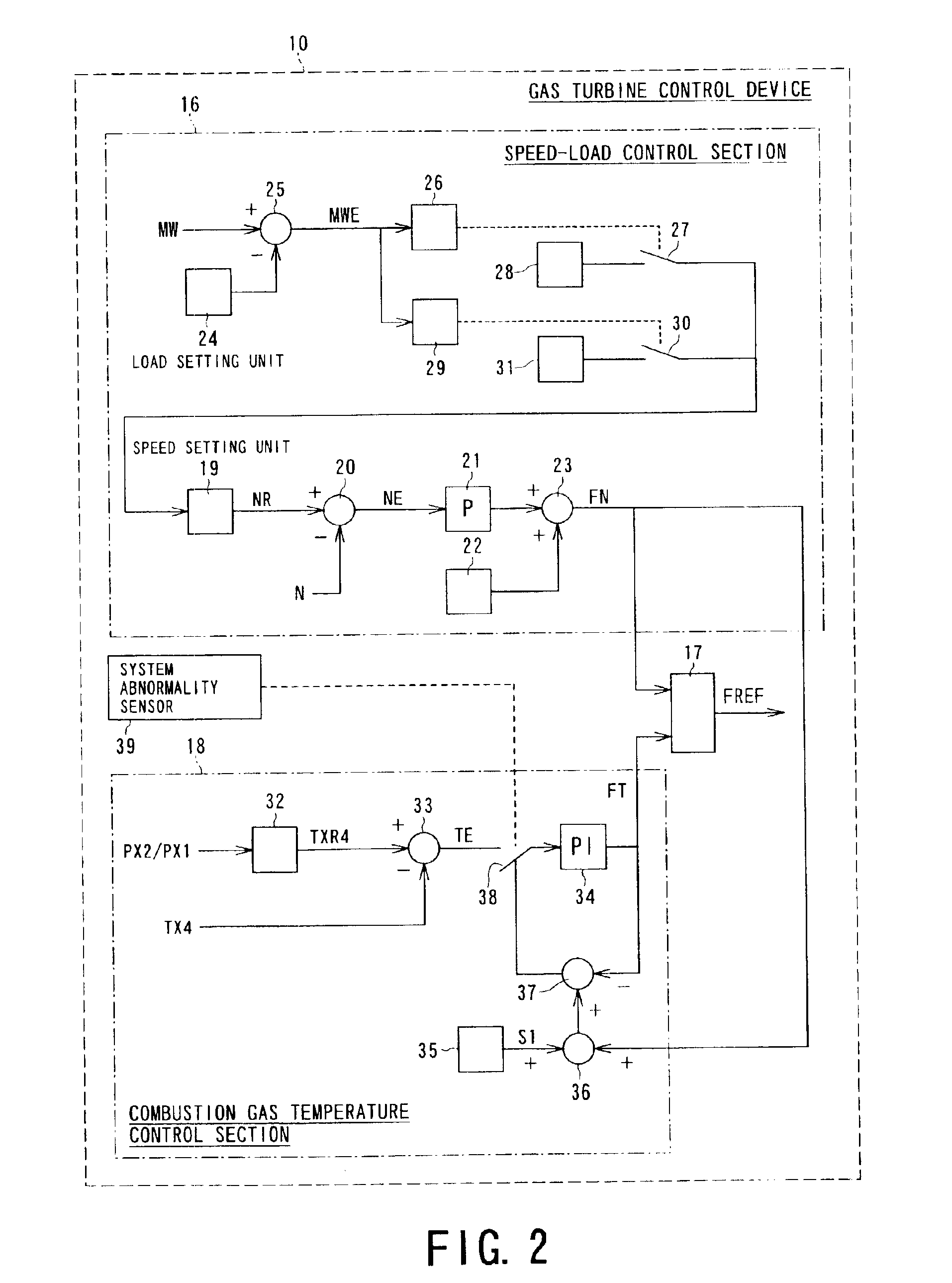
[0118]When such situation occurs in the prior art case shown in FIG. 37, the exhaust gas temperature signal FT is decreased and suppresses the increase of the exhaust gas temperature TX4, and the switching occurs to use the exhaust gas temperature signal FT in place of the speed-load control signal FN as the fuel control signal FREF. Therefore, there is no further increase of the fuel flow rate. In contrast, in the case of the invention shown in FIG. 2, the exhaust gas temperature control signal FT is adjusted to be greater than the speed-load control signal FN by the set value S1, in response to the signal from the system abnormality sensor 39. Therefore, the speed-load control signal FN and hence the fuel control signal FREF increase in response to the drop of the system frequency f and the gas turbine speed N, so that the fuel flow rate increases.

[0119]For this reason, it is possible to increase the system frequency f to restore the rated frequency by increasing the generator out...

fourth embodiment

[0126]FIG. 8 shows the invention. In the gas turbine control system 10 according to this embodiment, the fuel gas temperature control section 18 has a temperature setting unit 111, another temperature setting unit 112, a switch 42, a subtracter 33, and a proportional integrator 34 associated as shown. The temperature setting unit 111 generates a normal upper limit value TXR3a and the temperature setting unit 112 generates an emergency upper limit value TXR3b. When the system abnormality sensor 39 is not in operation, the switch 42 is changed over to the temperature setting unit 111, while when the system abnormality sensor 39 is in operation, the switch 42 is changed over to the temperature setting unit 112. When the system abnormality sensor 39 operates, the timer 40 begins to operate for a set period of time, and upon elapse of the set time the timer 40 interrupts the signal from the sensor 39 and changes over the switch 42 to the side of the temperature setting unit 111. The subt...

fifth embodiment

[0128]The subtracter 33 receives the limit value TXR3 from the temperature setting unit 111 or 112 as well as the combustion gas temperature TX3 from the arithmetic unit 113. The subtracter 33 outputs a temperature deviation TE, which is supplied to the proportional integrator 34 from which the combustion gas temperature control signal FT is output and sent to the fuel control signal selection unit 17. In this fifth embodiment, since the combustion gas temperature is not detected directly, but is calculated based on other detected values, both reliability of the detection of temperature and response in control are high.

[0129]FIGS. 10 and 11 show quantitative changes in the state of the gas turbine unit 100 using the gas turbine control system 10 shown in FIGS. 8 and 9. As shown in FIG. 10, as the generator output MW increases, the fuel flow rate GFX increases in proportion to the generator output MW. Until the generator output MW reaches the time point t1, the angle of the inlet gui...


PUM


Abstract

A gas turbine control system is disclosed which operates to stabilize the system frequency in a case of transitional variations of the system frequency without making the strength of hot gas path parts of the gas turbine below a maximum stress value of the hot gas path parts. When a system frequency abnormality is detected, the output of the gas turbine is adjusted to recover the system frequency by making a gas turbine combustion gas temperature control inoperative. For this purpose, there are provided a logical circuit operative to make the gas turbine combustion gas temperature control disabled or inoperative in response to an abnormal system frequency detection signal, and a recovery circuit that operates to cancel the inoperative state of the gas turbine combustion gas temperature control. The detection of an abnormal system frequency may be carried out by an outside signal. An abnormality detection unit may be provided in a combined cycle plant.

Description

BACKGROUND OF THE INVENTION[0001]1. Field of the Invention[0002]The present invention relates to a gas turbine control system which can prevent instability in the operation of a gas turbine which occurs when the system frequency increases or decreases in a short time from normal operational frequency due to disconnection of a load, an emergency stop of a generator and so on, and which can prevent an unstable operation as well as stoppage, which is the worst, of the gas turbine as a principal driving source of a thermal power generator, thus contributing to stabilizing the frequency of the electric power system during a transitional period.[0003]2. Description of the Related Art[0004]In gas turbine power generating plants, fuel and compressed air are supplied to a combustor and the combustion gas produced in the combustor is supplied to a gas turbine to operate the same. FIG. 36 shows a schematic view of a gas turbine power generating plant.[0005]A gas turbine unit generally designat...

Claims


Application Information

Patent Timeline
Patent Type & Authority Patents(United States)
IPC IPC(8): F02C9/28F02C9/00F02C9/46G05B23/02F02C7/042F02C9/54F04D27/00F04D29/56H02P9/04
CPCF02C9/28F02C9/32F02C9/54G05B23/0291Y02T50/67F05D2270/304F05D2270/303F05D2270/095F05D2270/091F05D2270/061F05D2270/024F05D2270/042F05D2270/06F05D2270/42Y02T50/60
Inventor HIRAYAMA, KAIICHIROUKOBAYASHI, TADASHIKOBAYASHI, SAYOKOKATAURI, TOMOOOOTSUKI, YASUHIKOMIZUNO, TAKASHI
Owner KK TOSHIBA
Why Eureka
Try Eureka