Method and apparatus for providing power to a microprocessor with integrated thermal and EMI management

Inactive Publication Date: 2005-09-20
MOLEX INC
View PDF148 Cites 28 Cited by
  • Summary
  • Abstract
  • Description
  • Claims
  • Application Information

AI Technical Summary

Problems solved by technology

Meeting end user performance requirements with minimal form-factors while increasing reliability and manufacturability presents significant challenges in the areas of power distribution, thermal management, and electromagnetic interference (EMD containment.
First, the lowered operating voltage of the processor places greater demands on the power regulating circuitry and the conductive paths providing power to the processor. Typically, processors require supply voltage regulation to within 10% of nominal. In order to account for impedance variations in the path from the power supply to the processor itself, this places greater demands on the power regulating circuitry, which must then typically regulate power supply voltages to within 5% of nominal.
While it is possible to place power conditioning circuitry on the processor package itself, this design is difficult to implement because of the unmanageable physical size of the components in the power conditioning circuitry (e.g. capacitors and inductors), and because the addition of such components can have a deleterious effect on processor reliability.
Such designs also place additional demands on the assembly and testing of the processor packages as well.
Further exacerbating the problem are the transient currents that result from varying demands on the processor itself.
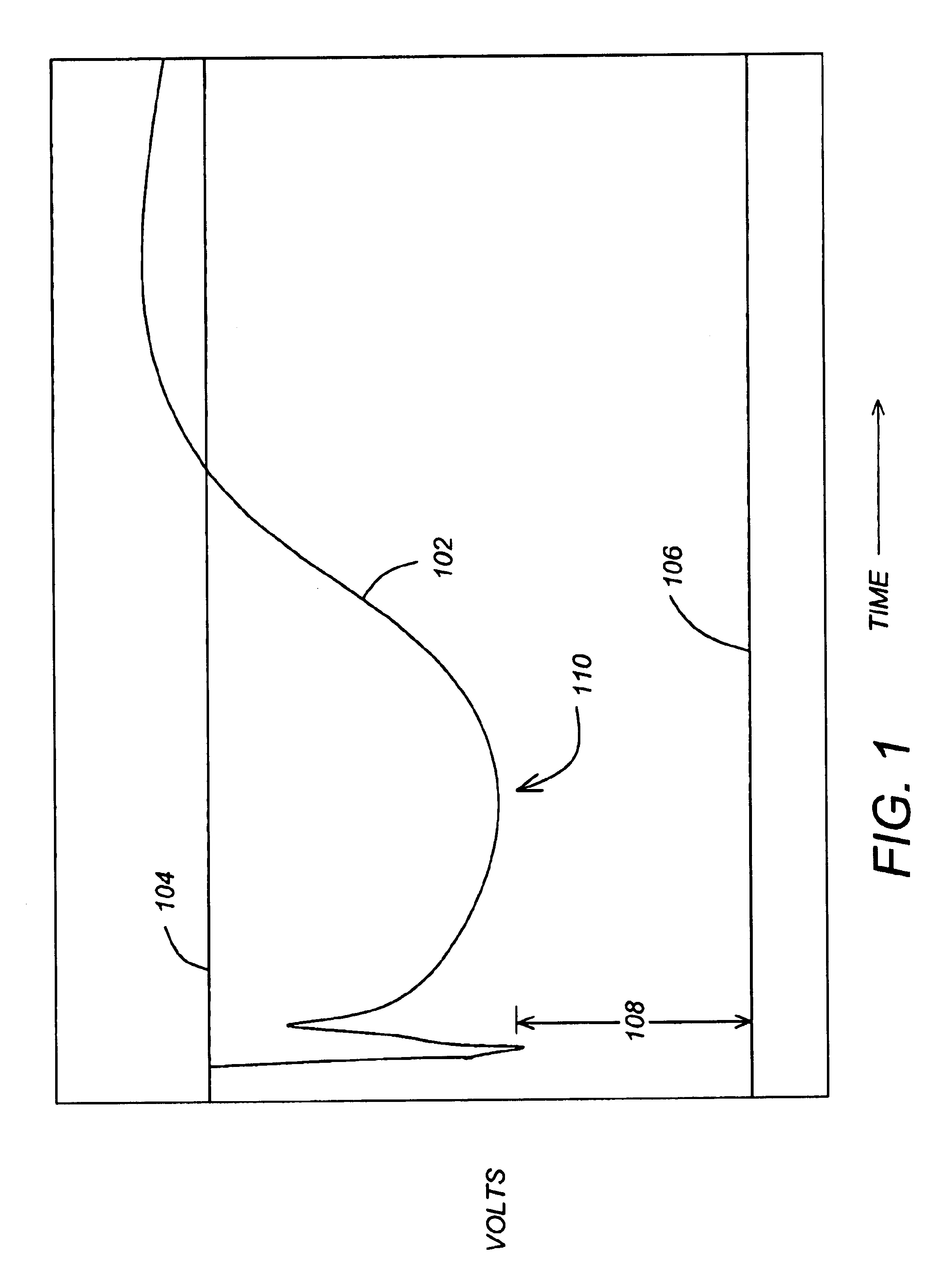
The resulting current surge between the processor and the power regulation circuitry can create unacceptable spikes in the power supply voltage (e.g. ⁢dv=IR+L⁢ ⁢ⅆiⅆt).
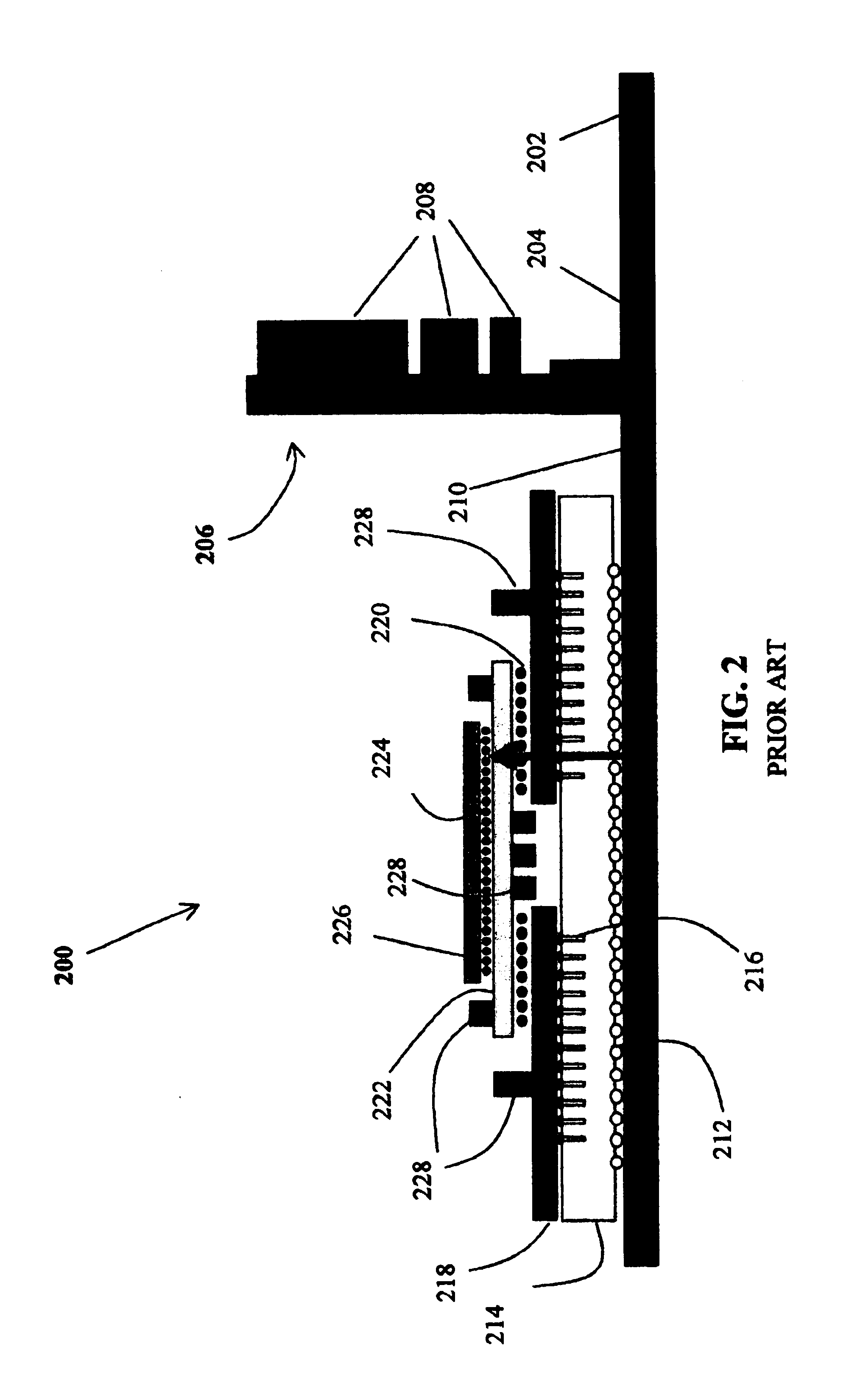
As described earlier distributed power systems such as is illustrated in FIG. 1 still result in unacceptable impedances that cause voltage drops in the power distribution path.
This not only increases costs, but consumer critical silicon area, chip package and board real estate.
In some cases, the resulting surface energy densities approach unmanageable levels.
Thermal management issues now present some of the largest obstacles to further processor miniaturization and increases in processor speed.
This makes it more difficult to locate the voltage regulator close to the CPU because the thermal management structures for each component conflict.
Electromagnetic interference (EMI) is also a problem.
However, using smaller apertures introduces thermal management problems because of decreased airflow.
Noise coupled from the processor package to the heat sink may cause the heat sink to act as an antenna and re-radiate the noise.
However, it is typically not possible to ground the heatsink through the processor package.
Also, while the grounding of the heatsink may reduce EMI, this technique is typically insufficient to meet EMI requirements, and additional shielding is typically necessary.

Method used


Image

  • Method and apparatus for providing power to a microprocessor with integrated thermal and EMI management
  • Method and apparatus for providing power to a microprocessor with integrated thermal and EMI management
  • Method and apparatus for providing power to a microprocessor with integrated thermal and EMI management

Examples


Embodiment Construction

[0362]In the following description, reference is made to the accompanying drawings which form a part hereof, and in which is shown, by way of illustration, several embodiments of the present invention. It is understood that other embodiments may be utilized and structural changes may be made without departing from the scope of the present invention.

i-PAK Architecture

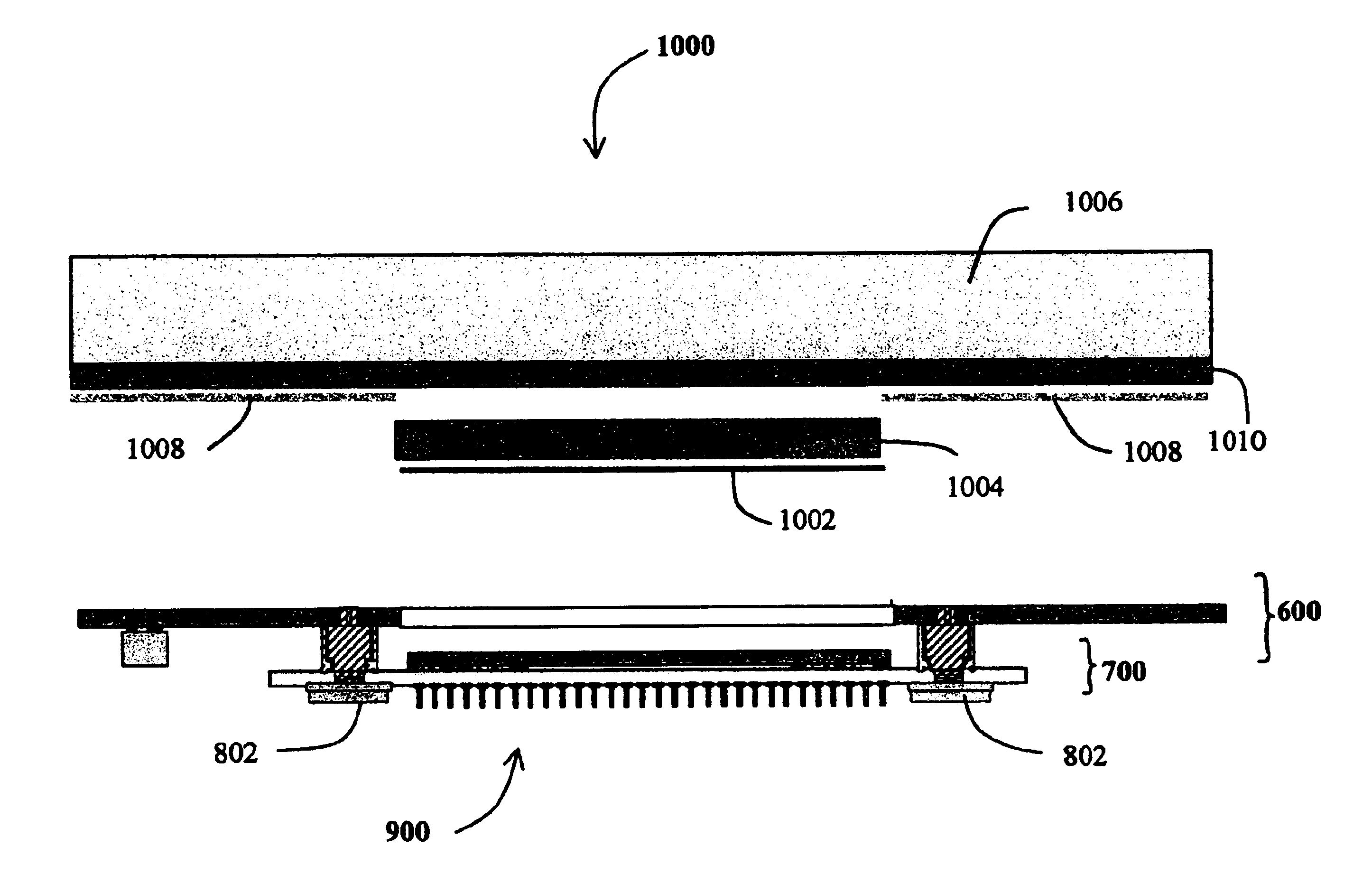
[0363]FIG. 3 is a diagram illustrating a typical microprocessor or electronic circuit package 300. A lid 304 which is usually composed of copper or other high thermal conductivity material is bonded to a substrate 302 using adhesive or metallurgical connection at junction 306. Also bonded to the substrate 302 is a microprocessor or electronic circuit 310. The connection between the substrate and the processor 310 can be made using solder balls (bumps) known as “flip-chip” or C-4 (controlled collapse chip connection). The physical gap between the substrate 302 and the processor 310 is occupied by a polymeric composite cal...


PUM


Abstract

A microprocessor packaging architecture using a modular circuit board assembly that provides power to a microprocessor while also providing for integrated thermal and electromagnetic interference (EMI) is disclosed. The modular circuit board assembly comprises a substrate, having a component mounted thereon, a circuit board, including a circuit for supplying power to the component, and at least one conductive interconnect device disposed between the substrate and the circuit board, the conductive interconnect device configured to electrically couple the circuit to the component.

Description

CROSS-REFERENCE TO RELATED APPLICATIONS[0001]This application claims benefit of the following U.S. Provisional Patent applications, which are hereby incorporated by reference herein:[0002]Application Ser. No. 60 / 301,753, entitled “INTEGRATED POWER DELIVERY USING HIGH PERFORMANCE LINEAR REGULATORS ON PACKAGE WITH A MICROPROCESSOR” by Joseph T. DiBene II, David H. Hartke, and Carl E. Hoge, filed Jun. 27, 2001;[0003]Application Ser. No. 60 / 304,930, entitled “Micro-i-PAK” by Joseph T. DiBene II, Carl E. Hoge, David H. Hartke, and Edward J. Derian, filed Jul. 11, 2001;[0004]Application Ser. No. 60 / 291,749, entitled “MICRO I-PAK ARCHITECTURE HAVING A FLEXIBLE CONNECTOR BETWEEN A VOLTAGE REGULATION MODULE AND SUBSTRATE,” by Joseph T. DiBene II, filed May 16, 2001;[0005]Application Ser. No. 60 / 291,772, entitled “I-PAK ARCHITECTURE POWERING MULTIPLE DEVICES,” by Joseph T. DiBene II, David H. Hartke, Carl E. Hoge, and Edward J. Derian, filed May 16, 2001;[0006]Application Ser. No. 60 / 292,125,...

Claims


Application Information

Patent Timeline
Patent Type & Authority Patents(United States)
IPC IPC(8): G06F1/18H01L23/427H01L23/433H01R4/64H01R12/16H05K1/02H05K1/14H05K3/30H05K3/36H05K7/10H05K7/20
CPCG06F1/18G06F1/182G06F1/189H01L23/427H01L23/433H01R4/64H05K1/141H05K1/144H05K3/368H05K7/1092H01R12/52H01R12/7088H01L2924/15192H01L2924/3011H05K1/0206H05K1/0262H05K1/0263H05K3/301H05K2201/10318H05K2201/10325H05K2201/1053H05K2201/10598H05K2201/10704H05K2201/10734H05K2201/2018H05K2201/2036H01L2224/73204H01L2224/16225H01L2224/32225H01L2924/00H01R12/721H01R12/7082H01L2224/32245H01L2224/73253H01L2924/16251H01L2224/92125H01L2924/00014H01L2924/15311H01L2224/0401
Inventor DIBENE, II, JOSEPH TEDHARTKE, DAVID H.
Owner MOLEX INC
Why Eureka
Try Eureka