Optimized combustion control of an internal combustion engine equipped with exhaust gas recirculation

a technology of internal combustion engine and exhaust gas recirculation, which is applied in the direction of electric control, machines/engines, mechanical equipment, etc., can solve the problems of increasing hydrocarbon emissions and particulate levels, increasing the temperature of the air intake manifold, and many of these techniques are incapable of meeting stricter emission standards, etc., to achieve the effect of preventing condensation and easy adjustment of moisture concentration

Inactive Publication Date: 2005-09-27
CLEAN AIR POWER
View PDF45 Cites 117 Cited by
  • Summary
  • Abstract
  • Description
  • Claims
  • Application Information

AI Technical Summary

Benefits of technology

[0018]The moisture measurements may also be used to prevent condensation in the engine's intake system. In this case, the measured parameter preferably is indicative of one of 1) the ambient relative humidity and 2) the relative humidity of the intake mixture. The engine can then be controlled, based on this measurement, to avoid condensation in the engine's air intake system. For instance, the adjusting step may comprise adjusting at least one of 1) a temperature of the intake mixture and 2) the moisture concentration of the intake mixture. The moisture concentration can most easily be adjusted by adjusting the setting of an exhaust gas recirculation valve controlling EGR flow to the intake system of the engine.

Problems solved by technology

However, many of these techniques are incapable of meeting stricter emission standards that are being implemented or will soon be implemented by the United States and many other countries.
However, application of EGR systems to diesel and other lean burn engines presents several distinct challenges.
For instance, the direct recirculation of hot exhaust gases to the air intake system of a diesel engine increases air intake manifold temperature, increasing hydrocarbon emissions and particulate levels due to deterioration in the combustion process.
In addition, soot and other particulates in the EGR system accumulate in the aftercooler and other components of the engine's intake and exhaust systems, decreasing the effectiveness of those components and shortening their useful lives.
Moreover, unlike in a throttled otto cycle engine, an unthrottled diesel engine often experiences an insufficient differential pressure across the EGR line to generate an EGR flow sufficient to obtain an optimal EGR mass fraction in the air / EGR mixture inducted into the engine.
However, the controls of prior EGR equipped engines do not take full advantage of EGR when attempting to reduce emissions or otherwise optimize combustion control.
If lambda drops below a minimum threshold, the reduced oxygen level in the combustion chamber increases NOx and other emissions to unacceptable levels.
On the other hand, if lambda rises above a maximum acceptable threshold, misfire can occur, resulting in excessive, unwanted emissions and sharply decreased thermal efficiency.
Lambda based controls therefore overestimate the reactability of the combustion mixture, leading to inaccurate calculations and resultant inferior controls.
Other standard combustion control strategies similarly fail to adequately take the oxygen concentration reducing effects of EGR into account.
This water vapor introduction has two effects, one potentially beneficial and one potentially harmful, neither of which has been adequately addressed by the prior art.
Nor does any known system actively control engine operation to obtain a specific desired water vapor concentration dependent parameter in the intake mixture.
Second, under some engine operating conditions, the water vapor may condense after it is mixed with ambient air.
This condensation can lead to accelerated corrosion of downstream components of the air intake system.
However, as should be apparent from the preceding paragraph, the removal of more water vapor than is required to avoid condensation results in reduced NOx reduction effectiveness due to the unnecessarily low moisture concentration of the intake mixture.

Method used


Image

  • Optimized combustion control of an internal combustion engine equipped with exhaust gas recirculation
  • Optimized combustion control of an internal combustion engine equipped with exhaust gas recirculation
  • Optimized combustion control of an internal combustion engine equipped with exhaust gas recirculation

Examples


Embodiment Construction

1. Resume

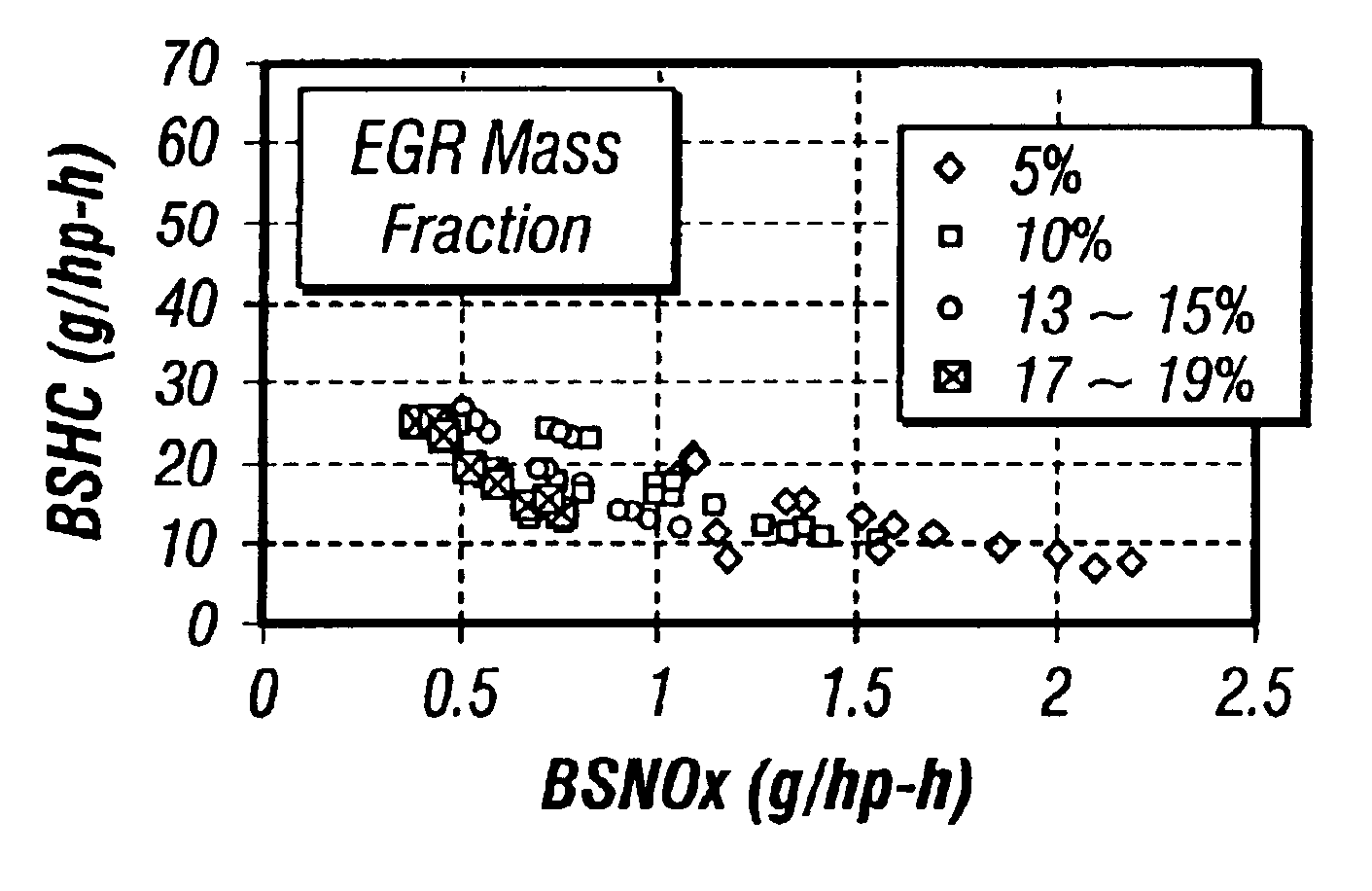
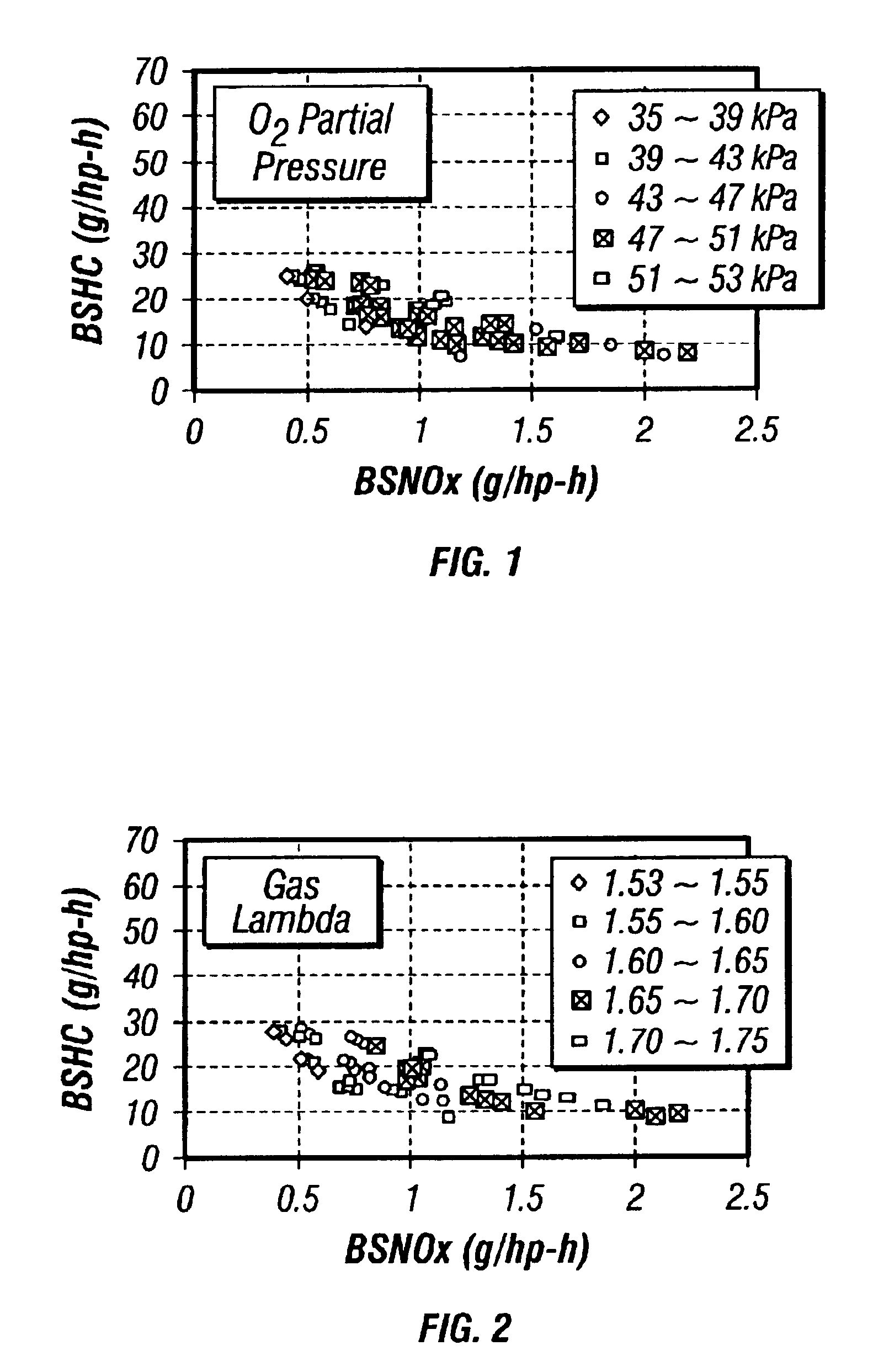
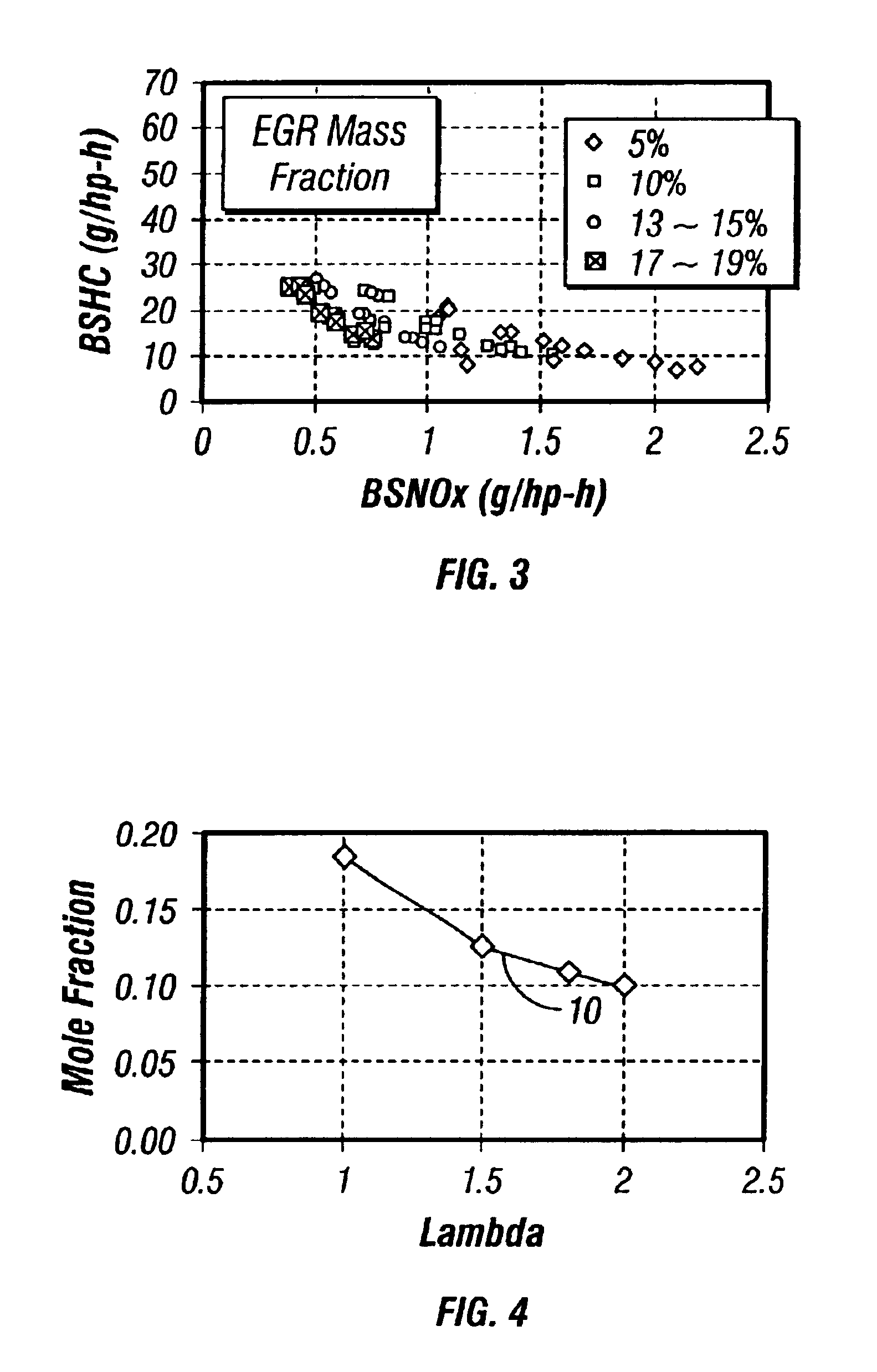
[0029]Pursuant to preferred embodiments of the invention, an EGR equipped internal combustion engine is controlled to maximize the beneficial effects and minimize the detrimental effects of EGR on engine operation. Specifically, at least one parameter indicative of the O2 concentration in the intake mixture and / or at least one parameter indicative of the H2O concentration in the intake mixture is monitored, and the monitored parameter is relied on to control one or more aspects of engine operation. For instance, for O2 dependent control, the O2 concentration in the intake gas stream can be monitored, and an excess oxygen ratio (EOR) or another oxygen partial pressure dependent parameter can be derived from the resultant data. The derived parameter can be used for open loop adjustment of another control strategy and / or can be used as the basis for a separate, closed loop control strategy designed to optimize that or a related parameter. As another example, a relative humidit...


PUM


Abstract

An EGR equipped internal combustion engine is controlled to maximize the beneficial effects and minimize the detrimental effects of EGR on engine operation. Specifically, at least one parameter indicative of the O2 concentration in the intake mixture and / or at least one parameter indicative of the H2O concentration in the intake mixture is monitored, and the monitored parameter is relied on to control one or more aspects of engine operation by open loop adjustment of other control strategies and / or by a separate closed loop control strategy. These controls are applicable to virtually any engine, and are particularly beneficial to lean burn engines such as diesel (compression ignition) engines, spark ignited natural gas engines, and dual fuel or other compression ignited natural gas engines. The engine may be equipped with either actively controllable EGR or passive and uncontrolled EGR.

Description

BACKGROUND OF THE INVENTION[0001]1. Field of the Invention[0002]The invention relates to internal combustion engines and, more particularly, relates to a system and method for controlling operation of an engine equipped with an exhaust gas recirculation (EGR) system.[0003]2. Discussion of the Related Art[0004]Countries worldwide are implementing ever-stricter emission(s) standards for diesel and other internal combustion engines. Past and some current standards for oxides of nitrogen (NOx), hydrocarbon (HC), and particulate emissions have been met through various improvements to engine design, advancements in fuel injection equipment and controls, etc. However, many of these techniques are incapable of meeting stricter emission standards that are being implemented or will soon be implemented by the United States and many other countries. Exhaust gas recirculation (EGR) is therefore becoming an increasingly important weapon in the war against emissions.[0005]EGR systems have been use...

Claims


Application Information

Patent Timeline
Patent Type & Authority Patents(United States)
IPC IPC(8): F02D41/14F02D41/00F02B47/00F02D41/40F02B43/00F02M25/07F02B47/08F02B29/04F02B3/00F02B3/06F02B29/00
CPCF02D19/024F02B43/00F02B47/08F02D41/0027F02D41/005F02D41/144F02D41/1454F02D41/40F02M25/0709F02M25/0722F02D19/10F02B3/06F02B29/0493F02D2200/0418F02M25/073F02M25/0731Y02T10/44Y02T10/32Y02T10/47F02M25/074Y02T10/36F02M21/0215F02B29/0406F02M26/06F02M26/19F02M26/27F02M26/28F02M26/35Y02T10/30Y02T10/40
Inventor WONG, HOI CHINGPAYNE, JOHNBECK, NIELS JOHANNES
Owner CLEAN AIR POWER
Why Eureka
Try Eureka