Method for producing a scattered radiation grid or collimator

Active Publication Date: 2005-10-04
SIEMENS HEALTHCARE GMBH
View PDF5 Cites 42 Cited by
  • Summary
  • Abstract
  • Description
  • Claims
  • Application Information

AI Technical Summary

Benefits of technology

[0016]On the basis of this prior art, it is an object of the present invention to provide a method for producing a scattered radiation

Problems solved by technology

These scattered beams, which, depending on the properties of the object, can cause up to 90% or more of the total signal response of an x-ray detector in diagnostic images, constitute an additional noise source and therefore reduce the identifiability of fine contrast differences.
This substantial disadvantage of scattered radiation is due to the fact that, owing to the quantum nature of the scattered radiation, a significant additional noise component is induced in the image recording.
However, this leads to a significant loss of primary radiation at the edges of the image recording, since a sizeable part of the incident primary radiation strikes the absorbing regions of the scattered radiation grid at these points.
The thickness of the absorbing structure elements or wall elements lying between the transmission channels or transmission slits, however, can lead to image perturbations by absorption of part of the primary radiation.
For example, in the case of matricially arranged detector elements, there is a risk of projection of the structures of detector elements and scattered radiation grids mutually interfering.
In the case of very short exposure times of, for example, 1-3 ms, however, stripes may also occur in the image if the movement speed of the grids is insufficient.
A particular disadvantage of all known scattered radiation grids is that the absorbing structure elements cannot be made arbitrarily thinly and precisely, so that a significant part of the primary radiation is always removed by these structure elements.
The same problem occurs in nuclear medicine, especially when using gamma cameras, for example Anger cameras

Method used


Image

  • Method for producing a scattered radiation grid or collimator
  • Method for producing a scattered radiation grid or collimator
  • Method for producing a scattered radiation grid or collimator

Examples


Example

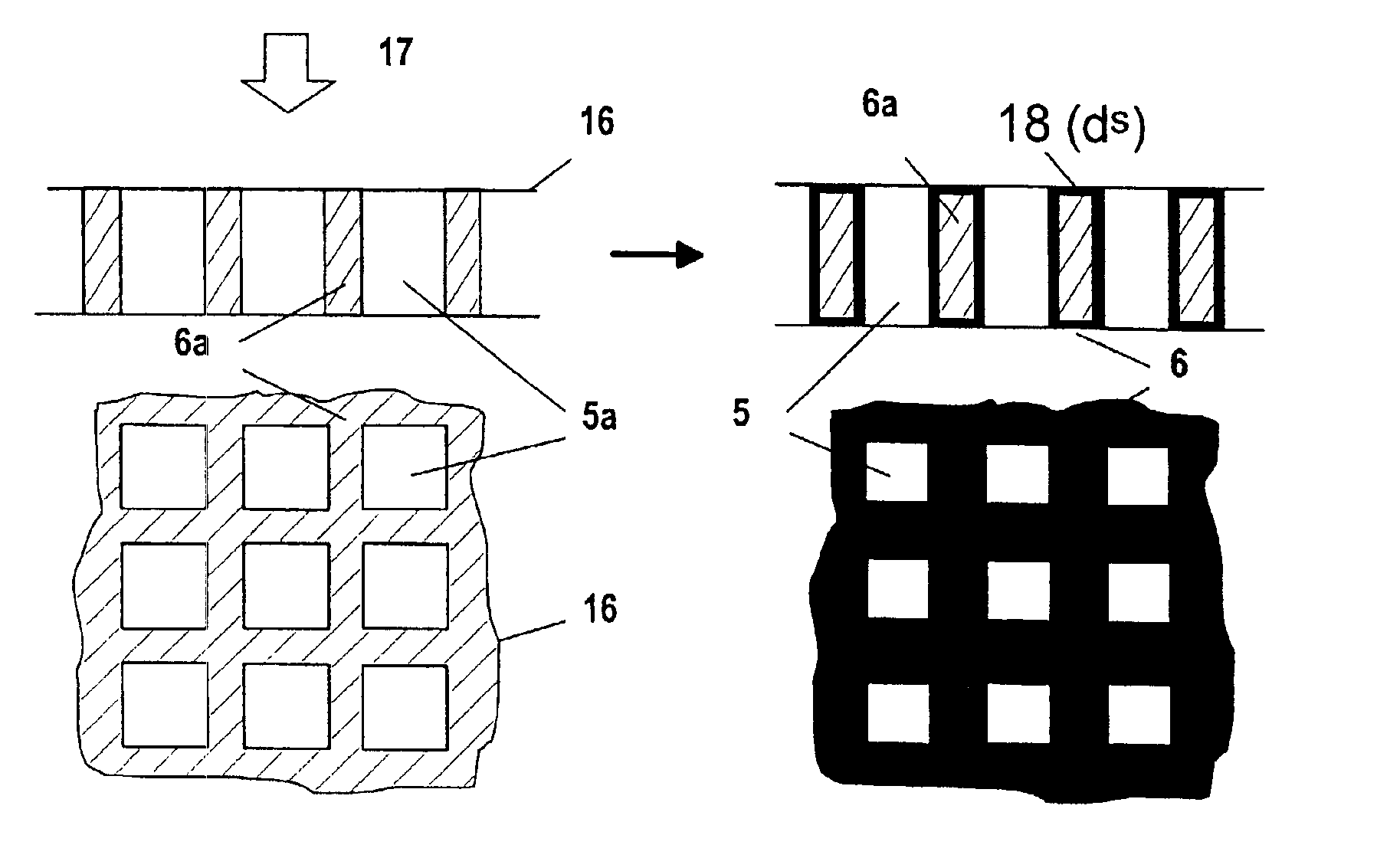
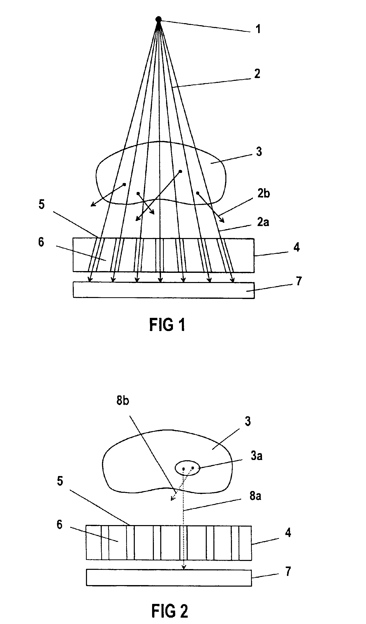
[0042]The typical situation when recording an x-ray image of an object 3 in x-ray diagnosis is represented schematically with the aid of FIG. 1. The object 3 lies between the tube focus 1 of an x-ray tube, which may be regarded as an approximately point x-ray source, and a detector surface 7. The x-rays 2 emitted from the focus 1 of the x-ray source propagate in a straight line in the direction of the x-ray detector 7, and in doing so pass through the object 3. The primary beams 2a striking the detector surface 7, which pass through the object 3 on a straight line starting from the x-ray focus 1, cause, on the detector surface 7, a positionally resolved attenuation value distribution for the object 3. Some of the x-ray beams 2 emitted from the x-ray focus 1 are scattered in the object 3. The scattered beams 2b created in this case do not contribute to the desired image information and, when they strike the detector 7, they significantly impair the signal-to-noise ratio. In order to ...


PUM

PropertyMeasurementUnit
Thicknessaaaaaaaaaa
Gamma radiationaaaaaaaaaa

Abstract

A method for producing a scattered radiation grid or collimator which, for an incident radiation type, has transmissive regions and nontransmissive regions of predeterminable geometry. First the geometry of the transmissive and the nontransmissive regions of the scattered radiation grid or collimator is set. On the basis of this geometry, a base body is constructed according to the geometry, optionally differing by a particular layer thickness, of the transmissive regions or the nontransmissive regions by a rapid prototyping technique through layer-wise solidification of a structural material under the action of radiation. On the basis of this base body, the scattered radiation grid or collimator is finally completed.

Description

FIELD OF THE INVENTION[0001]The present invention relates to a method for producing a scattered radiation grid or collimator, in particular for x- or gamma radiation.BACKGROUND OF THE INVENTION[0002]In radiography, stringent requirements are currently placed on the image quality of the x-ray images. In such images, as are taken especially in medical x-ray diagnosis, an object to be studied is exposed to x-radiation from an approximately point radiation source, and the attenuation distribution of the x-radiation is registered two-dimensionally on the opposite side of the object from the x-ray source. Line-by-line acquisition of the x-radiation attenuated by the object can also be carried out, for example in computer tomography systems. Besides x-ray films and gas detectors, solid-state detectors are being used increasingly as x-ray detectors, these generally having a matrix arrangement of optoelectronic semiconductor components as photoelectric receivers. Each pixel of the x-ray imag...

Claims


Application Information

Patent Timeline
IPC IPC(8): G21K1/02
CPCG21K1/025B33Y80/00
Inventor EIDAM, RICOHOHEISEL, MARTINSCHAFER, MARTINSKLEBITZ, HARTMUTSTRATTNER, PETER
Owner SIEMENS HEALTHCARE GMBH
Why Eureka
Try Eureka