
Secondary polymer layered impregnated tile

a technology of impregnated tile and polymer layered, which is applied in the field of low density polymeric resin impregnated ceramic articles, can solve the problems of reducing the flexibility of tiles, imposing a large weight penalty, and limiting the weight of scientific payloads, so as to improve the mechanical strength and thermal performance. , the effect of enhancing gas percolation

Inactive Publication Date: 2005-10-18
NASA +1
View PDF5 Cites 26 Cited by
  • Summary
  • Abstract
  • Description
  • Claims
  • Application Information

AI Technical Summary

Benefits of technology

This patent describes a low-density ceramic article that is impregnated with a polymer resin. The article has multiple layers of ceramic fibers, with the front layer containing a combination of ceramic and carbon fibers, the middle layer containing polymer-impregnated ceramic fibers, and the back layer containing ceramic fibers that are impregnated with a low-temperature pyrolyzing polymer. The article has increased mechanical strength and enhanced thermal performance. It can withstand severe heating environments and has a void volume to allow for enhanced gas percolation and prevent cracking. The polymer resin is uniformly distributed throughout the front layer and the back layer, and the article can form a char layer at its surface. The polymer resin is decomposed without depositing residue and the back layer is impregnated with a low-temperature pyrolyzing polymer that decomposes without depositing residue.

Problems solved by technology

It is the additional thickness of the material that imposes a large weight penalty for a spacecraft flying a long heat pulse trajectory, e.g., very high heat load.
This increased weight limits the weight of scientific payload.
When using tile TPS, the thickness makes the tile less flexible and increases material cost.
The disadvantage is that the high density of the final product increases the overall thermal conductivity of the system.
These products have a uniform density, however, which is a disadvantage in economizing the vehicle's weight.

Method used


Image

  • Secondary polymer layered impregnated tile
  • Secondary polymer layered impregnated tile
  • Secondary polymer layered impregnated tile

Examples


example 1

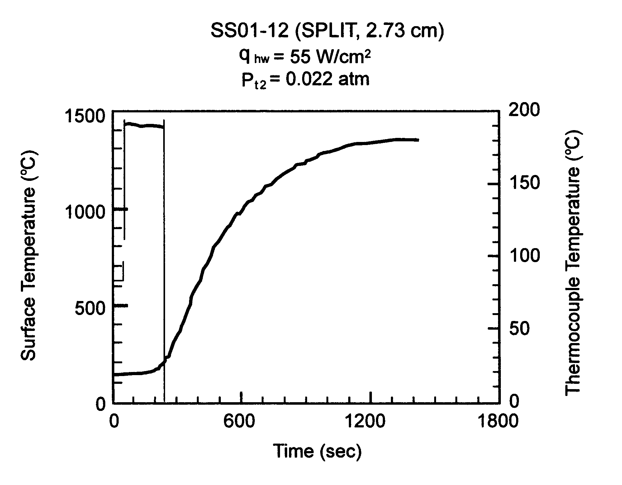
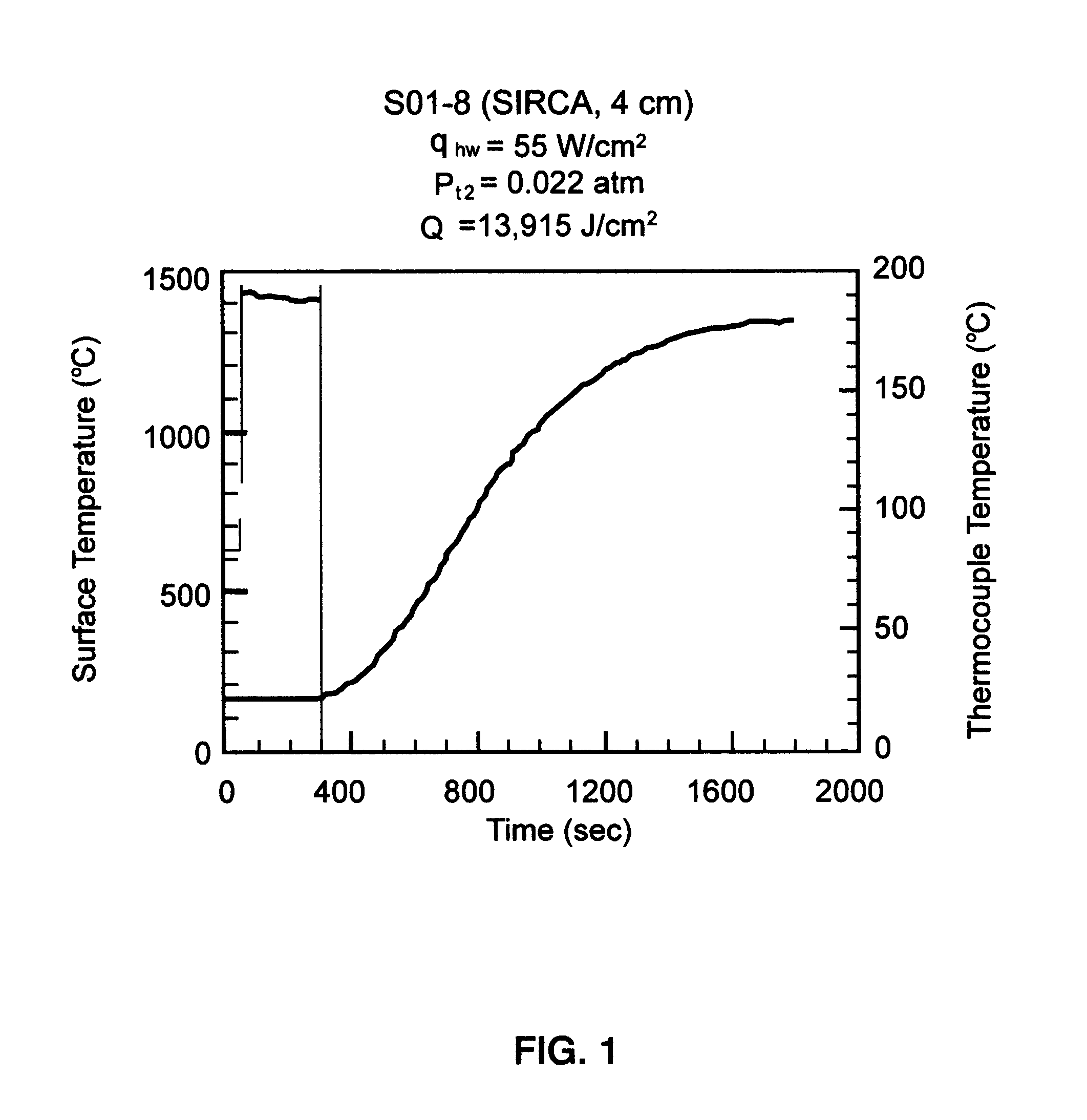
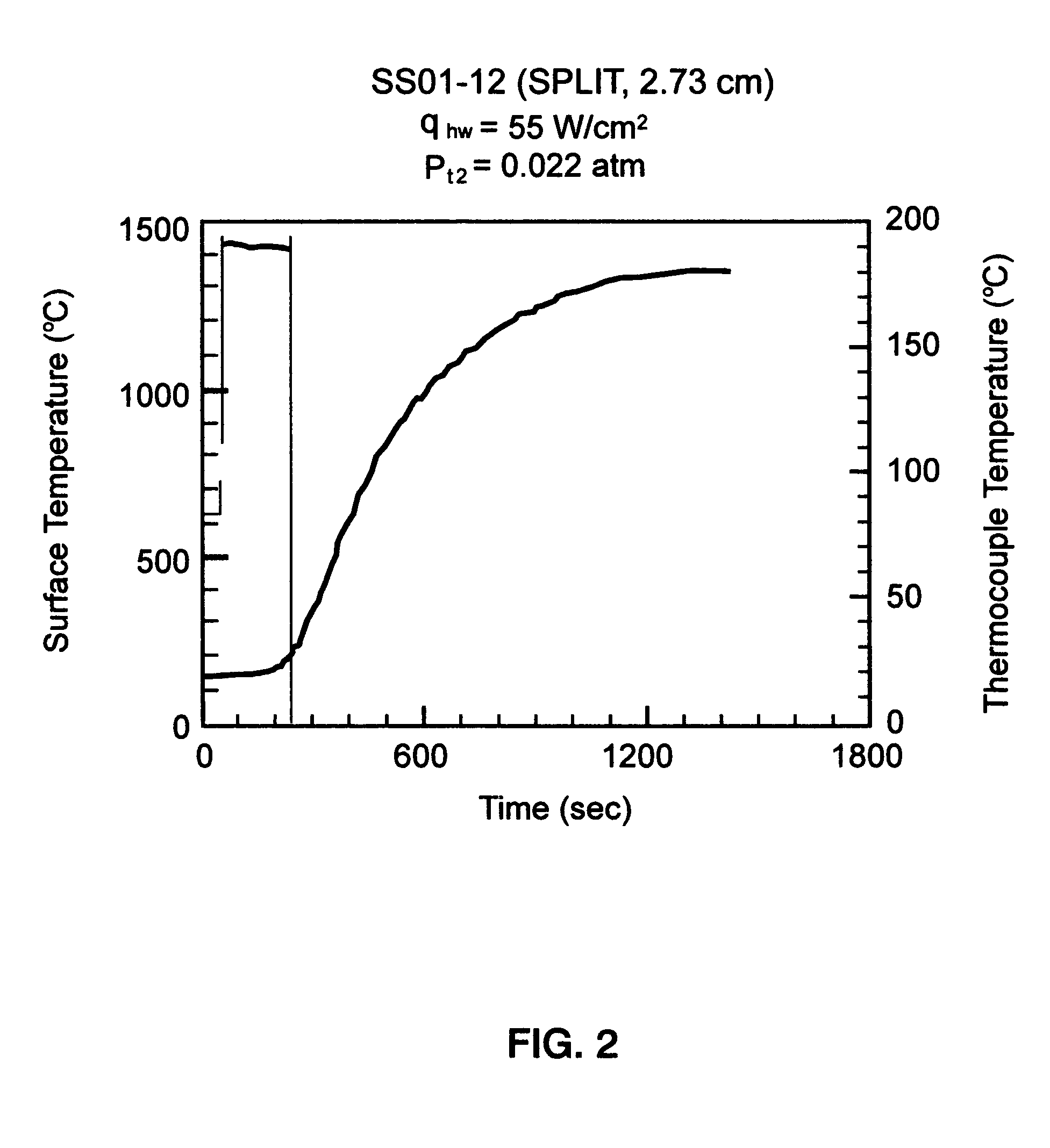
[0041]A ceramic article was prepared from a split SIRCA (silicone impregnated reusable ceramic ablator)-PMMA with the PMMA (polymethylmethacrylate) on the bottom of RTV silicone resins using a one-step process. In the one-step process a PMMA solution in ketone (MEK or acetone) or toluene was mixed with RTV 655 (silicone resin) solution in the same solvent. The two polymer solutions will not completely mix to form a homogeneous solution. Instead, a two-layer solution is formed with PMMA on the bottom layer. The location of this boundary line separating the two solutes depends on the amount of the polymers. It is desirable to impregnate more concentrated PMMA near the bottom surface of the SIRCA sample. When a 40% PMMA solution in MEK and a 10% RTV 655 solution in MEK (solvent can also be toluene) are mixed with a volume ratio of 1:9, the boundary line is about ¼ volume from the bottom. A light-weight tile impregnated by the solution containing one part of 40% PMMA and nine parts of 1...

example 2

[0046]In the two-step process, a solution of 30–40% PMMA in MEK (or in toluene) was prepared by dissolving 30–40 g of PMMA (mol. Weight=75000) in 70–60 g of solvent. A calculated amount (depending on the area and the desired depth of the PMMA penetration) of PMMA solution was impregnated on the front surface of the tile. After the solvent evaporated, the rest of the tile (the other side) was impregnated with an RTV 655 solution, then cured and dried. A TGA analyses of the dried sample showed that the bottom surface (0.1″) of the tile was primarily impregnated with PMMA and the rest of the tile was impregnated with RTV 655. An alternative two-step process was to brush the desired amount of PMMA solution on top of SIRCA tiles by brushing the same amount of solvent first. Toluene and alcohol solvents are preferred. If solvent evaporated before the desired amount of PMMA solution is brushed on, more solvent must be applied. Several cornicle cone shaped SIRCAs and split PMMA-SIRCAs were ...

example 3

[0049]When a PMMA solution as used to impregnate the PICA (phenolic impregnated carbon ablators) tile, the solvent (MEK or acetone) evaporated very fact. A PMMA film immediately forms on the surface which prevents further PMMA solution from penetrating into the PICA tile. It evaporates moderately when toluene is used as a solvent. A 30% PMMA (molecular weight of 75000) in toluene is coated on the surface of a PICA tile in about 0.1″ depth, and then dried at room temperature. Several PICA and split PMMA-PICA products were made and subjected to the arc-jet tests.

[0050]FIG. 4 shows the improvement that the PICA / SPLIT material afforded compared to the PICA material. Both materials had the same thickness and were exposed to the same heating environment. FIG. 4 shows the arc-jet data of PICA-15 (mono-polymer impregnation) and PICA / SPLIT at earth entry condition for a comet sample return capsule.

[0051]Two sets of models (one for baseline PICA material and one for PICA / SPLIT material) were ...


PUM

PropertyMeasurementUnit
widthaaaaaaaaaa
lengthaaaaaaaaaa
void volume fractionaaaaaaaaaa

Abstract

A low density organic polymer impregnated preformed fibrous ceramic article includes a plurality of layers. A front layer includes ceramic fibers or carbon fibers or combinations of ceramic fibers and carbon fibers, and is impregnated with an effective amount of at least one organic polymer. A middle layer includes polymer impregnated ceramic fibers. A back layer includes ceramic fibers or carbon fibers or combinations of ceramic fibers and carbon fibers, and is impregnated with an effective amount of at least one low temperature pyrolyzing organic polymer capable of decomposing without depositing residues.

Description

ORIGIN OF THE INVENTION[0001]The invention disclosed herein was made in the performance of work under a NASA Contract and is subject to Public Law 96–517 (35 U.S.C. §200 et seq.). The contractor has not elected to retain title in this invention.BACKGROUND OF THE INVENTION[0002]1. Field of the Invention[0003]This invention relates to low density polymeric resin impregnated ceramic articles comprising a plurality of layers of polymer impregnated ceramic fibers e.g. tile wherein the back layer of fibers of the multilayered article is impregnated with a low temperature pyrolyzing organic polymer and to the method for making the ceramic articles. The resin or polymer impregnated ceramic articles are particularly useful as structural ceramic ablators in thermal protection systems (TPS) such as an ablative heat shield for high speed atmospheric entry vehicles. The ceramic articles of this invention are structurally stable, and can be easily manufactured to accommodate specific end-use requ...

Claims


Application Information

Patent Timeline
Patent Type & Authority Patents(United States)
IPC IPC(8): B32B18/00C04B35/14C04B35/80C04B35/83
CPCB32B18/00C04B35/803C04B35/83C04B35/14Y10T428/269C04B2235/3418C04B2235/5224C04B2235/5232C04B2235/5244C04B2237/58C04B2235/6567C04B2235/658C04B2237/341C04B2237/343C04B2237/365Y10T428/1372Y10T428/252Y10T428/30C04B35/80Y10T428/249968Y10T428/249978Y10T428/249986
Inventor TRAN, HUY K.RASKY, DANIEL J.SZALAI, CHRISTINE E.CARROLL, JOSEPH A.HSU, MING-TA S.
Owner NASA
Learn More