Rotor assembly, information-recording/-reproducing device using the rotor assembly and method of assembling the rotor assembly

Inactive Publication Date: 2005-11-15
PANASONIC CORP
View PDF15 Cites 17 Cited by
  • Summary
  • Abstract
  • Description
  • Claims
  • Application Information

AI Technical Summary

Benefits of technology

[0053]The jig made of soft magnetic material enables to have the magnetic fields escaping from rotating magnet concentrated to the soft magnetic material. In the process of bonding a rotating magnet to a disc portion having a recording medium formed thereon, when the disc portion is heated in order to have a thermosetting adhesive, or the like gluing material whose curing can be accelerated by heat, cured, the recording medium whose

Problems solved by technology

Operating environments of portable apparatus, however, are much harsher than those of personal computers.
However, even if an instantaneous impact caused the rotating portion to be withdrawn from stationary supporting means for a substantial amount, the head supporting mechanism as well as the recording medium itself might be destroyed.
If a rotating body is withdrawn substantially, a lubricant provided in a gap between the axle and bearing sleeve spills out and the bearing becomes unable to operate.
Furthermore, the sputtering lubricant may well stain the disc portion.
It is also difficult to bring the centers of flange portion and recording medium 802 to be concentric to the axis of rotation.
So, a recording density of a recording medium 802 is subject to these factors, which means that there is a limit in the efforts for increasing the recording density of a recording medium.
Improving the accuracy level with the number of components in the above-described configuration, however, the cost for such production facilities will be substantial, which means that it is not practical.
However, there have been no proposals so far regarding a shape of disc portion that can withstand a shock when it is incorporated in a portable apparatus.
There have been still other problems left to be solved; when the diameter of disc portion is reduced it turns out to be difficult to keep a stable levitation of head slider, and to maintain a sufficient strength at the outer circumference.
Under such a case, the

Method used


Image

  • Rotor assembly, information-recording/-reproducing device using the rotor assembly and method of assembling the rotor assembly
  • Rotor assembly, information-recording/-reproducing device using the rotor assembly and method of assembling the rotor assembly
  • Rotor assembly, information-recording/-reproducing device using the rotor assembly and method of assembling the rotor assembly

Examples


Example

(Embodiment 1)

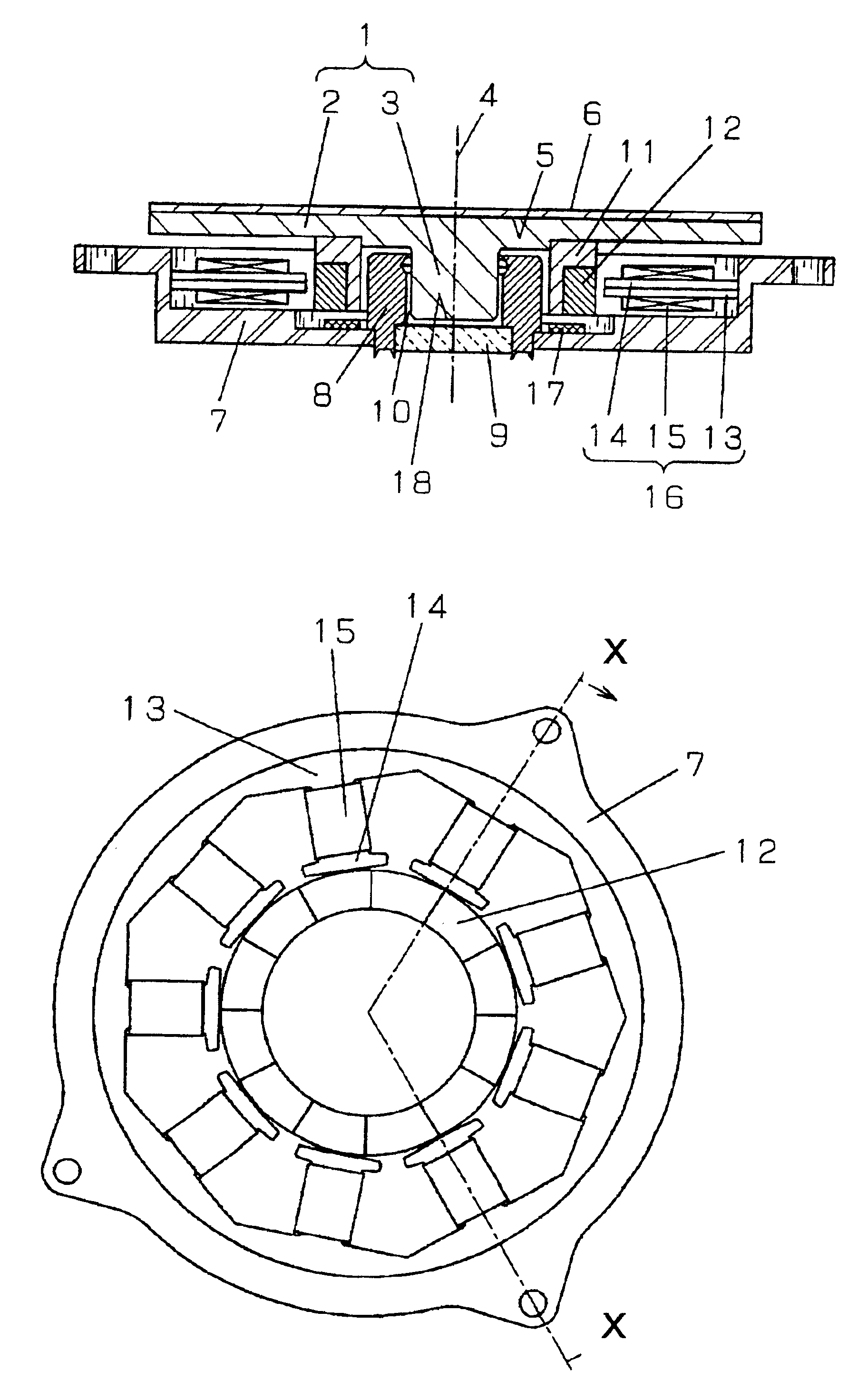
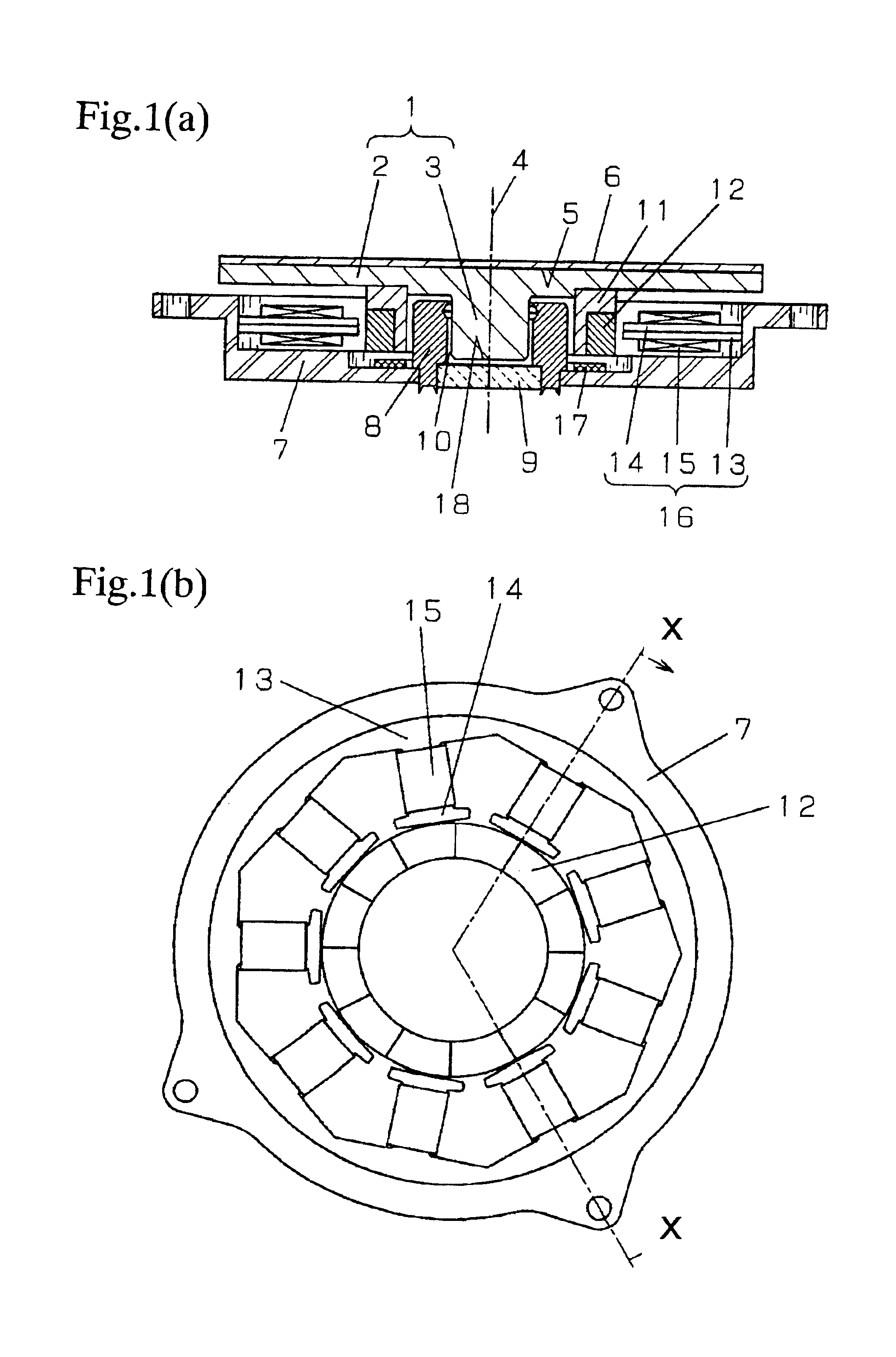
[0100]FIG. 1(a) and FIG. 1(b) show a disc device in accordance with a first exemplary embodiment of the present invention. FIG. 1(a) is a cross sectional view sectioned along X—X of FIG. 1(b); FIG. 1(b) is the plan view with the rotating portion excluded.

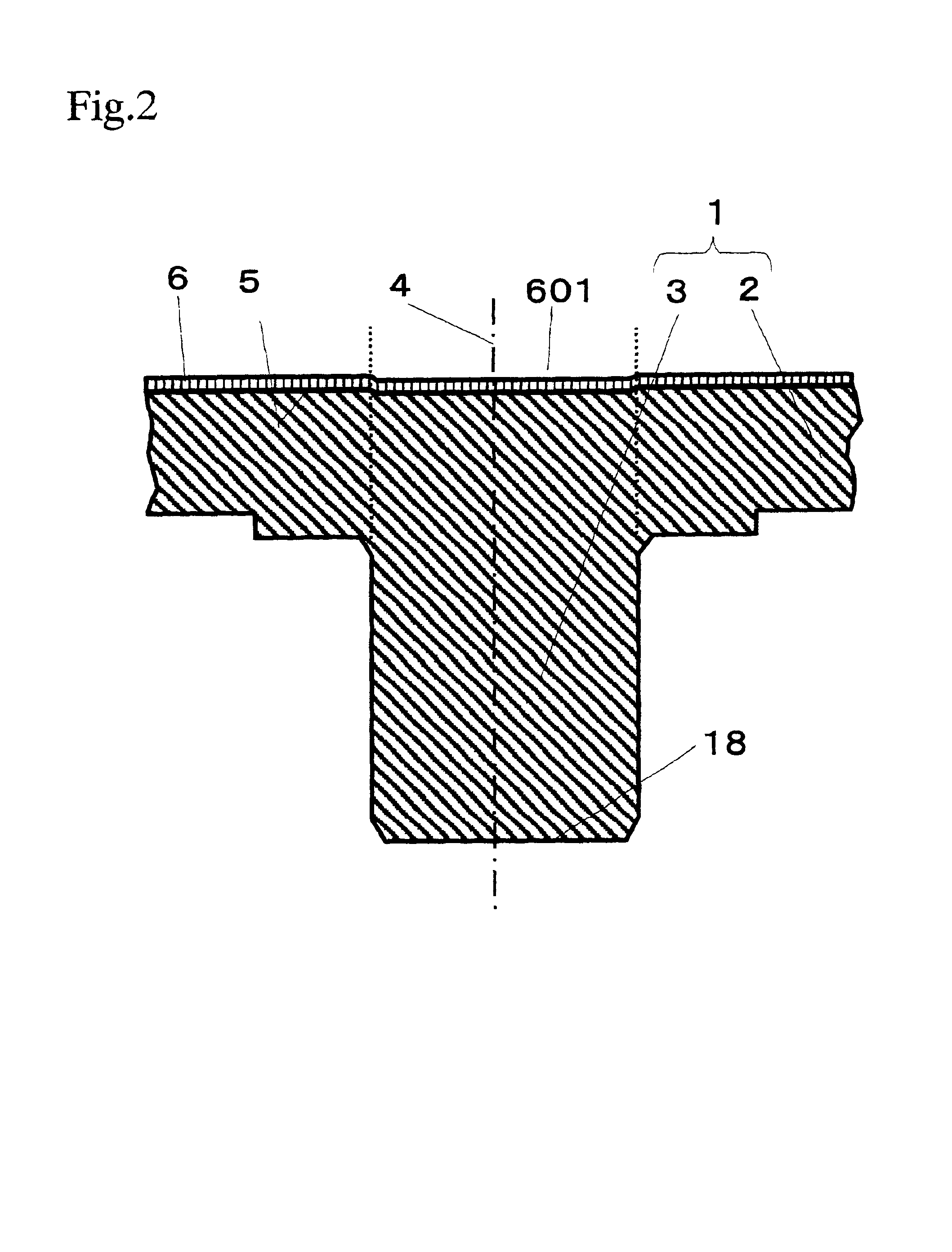
[0101]Referring to FIG. 1(a), a rotating disc (this constitutes the rotor of a motor, so hereinafter referred to as rotor assembly 1) is formed of a disc portion 2 and a round column portion 3. The rotor assembly 1 is integrally formed using, for example, glass, liquid crystal polymer, PPS (polyphenylene sulfide), or the like thermoplastic material, or an Al alloy metal. A thermoplastic material may be formed by means of press formation, or casting formation after melting. There is no specific restriction in selecting the glass material; generally-used soda lime glass, aluminosilicate glass, aluminoborosilicate glass, borosilicate glass, etc, may be used. It may undergo a surface reinforcement process, by a chemical me...

Example

(Embodiment 2)

[0150]A second exemplary embodiment of the present invention is described with reference to FIG. 15. FIG. 15(a) is a cross sectional view of the key portion with a focus on the bearing part, FIG. 15(b) is a partial magnification. Those parts having the functions identical to those in the embodiment 1 are represented by using the same symbols as in FIG. 1.

[0151]Referring to FIG. 15(a), an axle 101 containing within it the rotating axis 4 is fixed on the base 7. A rotor assembly 1 is formed of a disc portion 2 provided with information recording layer 6 of a certain thickness disposed on the main surface 5 so that it crosses at right angle with the rotating axis 4 and a rotating cylindrical portion 102 provided integrally on the disc portion 2 in a surface opposite to the main surface 5. The rotor assembly 1 may be formed in the same manner as in embodiment 1, using a liquid polymer, PPS, or the like thermoplastic material, or an Al alloy metal.

[0152]The surface of disc ...

Example

(Embodiment 3)

[0173]A third exemplary embodiment of the present invention is a modification in the shape of disc portions in the embodiments 1 and 2. The modification is aimed to reduce amount of flexion caused by a shock, and to reduce a possibility of damage due to collision of head slider and the disc caused by an impact given on the disc portion. FIG. 18 shows shape of a rotor assembly in embodiment 3. FIG. 19 is a cross sectional view showing key part of the magnetic disc attached to driving means. The rotor assembly 1 is integrally formed of a disc portion 2 having at one of the surfaces a flat surface and a round column portion 3, or the rotating axle, provided at the center of the other surface. The disc portion 2 is provided on the surface having the round column 3 with a slope 502a stretching continuously in a straight line from a place of circle V towards the outer circumference edge, a magnet surface 502b for fixing a rotor yoke 73 and a rotating magnet 74, and a flat su...


PUM


Abstract

An information-recording/-reproducing device comprises a rotor assembly formed of a disc portion having information recording layer provided on the main surface and an axle portion, the disc portion being connected at the center of a surface opposite to the main surface with the rotating axle so that the rotating axis crosses at right angle with the main surface of disc portion at the center of rotation, a bearing for supporting the axle of disc portion freely rotatable, a rotating magnet fixed to a rotor yoke, a stator disposed opposing to the rotating magnet, and a motor for rotating the disc portion with the rotating axis of the axle as the center of rotation. Preferably, the disc portion with the rotating axle portion having a round column shape or a cylindrical shape, further may have a shallow hollow in the central part of the main surface which being a surface opposite to the surface having the rotating axle.

Description

FIELD OF THE INVENTION[0001]The present invention relates to an information-recording / -reproducing device using a magnetic disc, an optical disc or the like information recording medium; more specifically, a rotor assembly for high density recording and reproducing of stored information, and an information-recording / -reproducing device incorporating the rotor assembly. A method of assembling the rotor assembly is also included in the present invention.BACKGROUND OF THE INVENTION[0002]The technology development is proceeding very fast in the field of information-recording / -reproducing device using a magnetic disc or the like information recording medium (hereinafter which device is referred to also as disc device). As a result, the disc devices are finding many new application fields, besides the conventional computer-related uses, and various portable electronic appliances, such as the cellular phones, PDAs (Personal Digital Assistances), digital cameras, for example, are familiar i...

Claims


Application Information

Patent Timeline
IPC IPC(8): G11B19/20
CPCG11B19/2009F16C17/107F16C2370/12G11B19/20
Inventor OBATA, SHIGEOMATSUOKA, KAORUSHINOHARA, KOICHIUENO, YOSHIHIROINAGAKI, TATSUHIKOKUWAJIMA, HIDEKIKITA, HIROMI
Owner PANASONIC CORP
Why Eureka
Try Eureka